Frahan StonePack: An Applied Thesis in Support of the Software¶
Pre-CAM Stone Fabrication-Readiness for Rhino and Grasshopper¶
Author: Independent Research Date: 2026-06-13 Open data. Open source. No university affiliation.
Nature of this thesis¶
This is an applied thesis. Its primary contribution is the software itself, the Frahan StonePack Grasshopper plug-in, and this document exists to support that software development: to derive the mathematics each subsystem implements, to classify every component by originality against the published literature, and to validate the results on the Rhino canvas. It is not a theoretical treatise that a tool happens to accompany. It is the written account of an applied research-and- development effort whose deliverable is the running system. The reader should treat the code, the benchmarks, and the example definitions as the primary evidence, and this document as their structured explanation. Every chapter therefore takes one shipping subsystem and answers three engineering questions about it: what published method does it implement, how was that method derived and evolved in code, and what does the validated result look like in practice.
Abstract¶
Frahan StonePack is a pre-CAM fabrication-readiness bridge for natural
stone, built as one Grasshopper plug-in (Frahan.StonePack.gha) over a
Rhino-free algorithmic core. It sits between design intent and machine-ready
fabrication and answers the questions a CAM package assumes are already
solved for stone: which block to take from a quarry, on which planes to cut
it, in what order, oriented how, packed against which neighbours, and stable
under gravity once set. The system carries two design flows as equals.
Top-down, a target form is imposed and the stone is found or cut to realise
it. Bottom-up, the stock is given and the form emerges from it. A single
data-flow spine, ingest to process to segment to pack-or-cut to stabilise to
fabricate, runs through every workflow, and one shared numeric-hygiene layer
(recenter, scale-relative epsilon, one reconciled tolerance budget) keeps a
pipeline that spans seven orders of physical scale numerically honest.
The originality posture is deliberately conservative and evidence-led. Every
component carries an [Algorithm] attribute naming its published source, so
each can be classified honestly: clean-room math built from a citation,
evolved fork over a documented baseline, facade over our own primitives,
vendored permissive library, or flagged original research pending a
prior-art sweep. The repository's research contributions are measured against
the shipping implementation as the baseline, never a re-implementation, and
benchmark numbers are reported, not claimed validated, until seen on the
canvas. Licensing is tracked the same way: copyleft and non-commercial
obligations are quarantined behind optional native shims and an isolated
research-only assembly, so the default install links no copyleft code.
Table of Contents¶
Front matter¶
Chapters¶
- 01. Two-Dimensional Nesting and Trencadís
- 02. Three-Dimensional Packing and Settling
- 03. Quarry Block-Cutting Optimization
- 03b. Point-Cloud Discontinuity Extraction, Joint Sets, and the DFN
- 04. GPR Fracture and Cavity Mapping
- 05. Masonry Equilibrium and Cyclopean Reassembly (CRA)
- 06. Voussoir Geometry and Stereotomy
- 07. Surface Packing and Conformal Unwrapping
- 08. Edge-Matching and Fragment Reassembly
- 09. Kintsugi and Learned 6-DoF Pose
- 10. Mesh Processing and Surface Reconstruction
- 11. Fabrication, Sculpting and Carving
- 12. Data Ingestion and Format Readers
- 13. Lab, Analysis and Reporting
- 14. Workflow Architecture and Data-Flow Connections
- 15. Evolution: From Baselines to the Current System
Back matter¶
How to read this thesis¶
Chapter 0 establishes the assembly layering, the ribbon, and the shared numeric foundations that every later chapter stands on. The numbered chapters each take one ribbon subsystem, derive its mathematics (including the original derivations where the repository evolved the math), classify its components by originality with file-and-line evidence, and embed visually validated example renders. Chapter 14 is cross-cutting: it maps how the per-subsystem algorithms connect into the end-to-end workflows of the data-flow spine.
The three back-matter documents are binding. The Originality Matrix
(90_originality.md) is the single honest ledger of what is built from
scratch, what extends prior work, and what is vendored, with the per-component
evidence and the full licensing flag register. The Roadmap (91_roadmap.md)
is the consolidated, deduplicated and prioritised list of what is left to do,
graded by severity. The Bibliography (99_references.md) returns every cited
work, keyed [Rn] for stable cross-reference.
A result in this thesis is true only when visually validated in Rhino
(AGENTS.md criterion c). Numbers from the headless harness are measured, not
validated, until seen on the canvas. The example renders below are the
visually validated forms.
Status (2026-06-13): complete. All fifteen chapters are written, and the three back-matter ledgers are consolidated across all fifteen: the Originality Matrix classifies 109 component families (clean-room 59, facade-over-primitives 20, evolved-fork 9, original-research 8, vendored-library 5, wrapper-of-native 5, direct-port 3) with file-and-line evidence and a thirteen-flag licensing register; the Roadmap consolidates every chapter's open items by severity; and the Bibliography returns every cited work, citation-normalised.
Addendum (2026-07-05, v0.1.0-alpha release): the chapters above are kept as the historical record of the system at completion; the research that shipped between completion and the public release (2D-nest consolidation, the edge-matching theory audit, the quarry-geology feasibility set, vault form-finding, and the verified robot handoff) is summarised in the Post-completion addendum at the end of this document, with pointers to the wiki studies and the shipped examples.
Chapter 0 — Repository Overview and Cross-Cutting Foundations¶
Author: Independent Research. Open data, open source. No university affiliation.
This chapter states what Frahan StonePack is, how the assemblies are
layered, what the ribbon offers, and the shared numeric foundations that
every algorithm in later chapters stands on. The conventions follow
AGENTS.md: a result is true only when visually validated in Rhino
(criterion c); numbers from the headless harness are measured, not
validated, until seen on the canvas.
0.1 What the project is¶
Frahan StonePack is a pre-CAM stone fabrication-readiness bridge for Rhino and Grasshopper. It sits between design intent and machine-ready fabrication. It is not a CAM system and does not generate toolpaths as its product. It answers the questions a CAM package assumes are already solved for natural stone: which block out of this quarry, cut on which planes, in which order, oriented how, packed against which neighbours, and stable under gravity once set. The output is a fabrication-ready geometric plan with stone metadata attached, which a downstream CAM or robotic-setting stage then consumes.
The project carries two design flows as first-class citizens.
- Top-down (form-first). A target form is given, and the system finds or cuts the stone to realise it: voussoirs for an arch or vault, a sculpture decomposed into masonry-scale blocks, a quarry block cut to yield a designed shape. Imposition of intent onto material.
- Bottom-up (material-first). The stock is given, and the form emerges from it: random rubble walls, vein-flow and live-edge selection, Trencadis mosaics from fragments. Negotiation with material.
The application domain is dimension and monument stone, with a working emphasis on granite (Tamil Nadu deposits, where joints in poorer rock drive the GPR ambition) and on marble and limestone for the bench-to-block yield studies. The spine runs from sub-surface sensing through to a setting plan, so the same repository carries ground-penetrating-radar fracture mapping, LiDAR and photogrammetry ingest, mesh reconstruction, 2D and 3D packing, masonry assembly with contact equilibrium, and fabrication export.
0.2 Assembly and layer architecture¶
The solution under src/ is layered so that the algorithmic core never
depends on Rhino. This keeps the math headless-testable and lets the same
engine run inside Rhino, inside a benchmark harness, or inside an
out-of-process worker.
| Assembly | Target | Role |
|---|---|---|
Frahan.StonePack.Core |
net48, Rhino-free | All geometry and solver math. Plain double arrays and Frahan-owned structs (Vec3, Size3, Box3). 11 sub-namespaces. |
Frahan.EdgeMatching.Core |
net48, Rhino-free | Fragment edge-matching and reassembly (boundary rails, projection bootstrap, soft-ICP / L-BFGS). |
Frahan.Kintsugi.Port |
net48, Rhino-free | Learned 6-DoF fracture-reassembly port with a verifier gate (see licensing note below). |
Frahan.RubblePack |
net48 | Multi-bin rubble packing front end. |
Frahan.StonePack.GH |
net48, Grasshopper | The facade. Converts RhinoCommon to Core types at the component edge, calls Core, converts back. Builds to ONE Frahan.StonePack.gha. |
Frahan.StonePack.Rhino |
net48, RhinoCommon | Rhino plug-in surface (commands, document hooks). |
The boundary rule is strict and load-bearing for the thesis claim of
clean, reusable math. The Core takes no using Rhino. Components in the
GH layer translate at their input/output edge only. This is why the
packing benchmarks (--packbench, --pack2dstudy) and the unit tests
run with no Rhino present, and why the same BlockCutOptSolver is the
baseline the research chapters evolve rather than a re-implementation.
Native bridges are reached through a lazy boundary, not a hard link. The
default install ships no native DLL. NativeBridge.cs and
NativeBackendLoader probe a fixed search path on first use, fall back to
a managed default with a surfaced remark if the DLL is absent, and never
throw on a missing backend. The FRAHAN_BACKEND environment variable
forces a specific backend for testing. The native shims live under
native/ and are reached via P/Invoke:
| Bridge | Library | License | What it does | Citation |
|---|---|---|---|---|
nfp_kernel |
Clipper2 (vendored, unmodified) | BSL-1.0 | Batched No-Fit-Polygon Minkowski sums for the 2D nester; one native call per part replaces the managed Clipper2 loop. Measured ~8x wall-time on the 7-shield bench. | (Johnson, Clipper2) |
| Clipper2 (managed) | Clipper2 adapter | BSL-1.0 | Vatti-derived polygon clipping for 2D Boolean and overlap validation. | (Johnson, Clipper2) |
cgal_shim |
CGAL Polygon Mesh Processing | GPLv3 / commercial | Robust non-convex mesh-mesh Boolean (corefinement, EPECK/EPICK hybrid), straight skeleton, SDF segmentation, heat-method geodesics, PMP repair. | (CGAL PMP) |
geogram_shim |
Geogram v1.9.9 | BSD-3 | Mesh repair, hole filling, remesh and decimation, restricted Voronoi, constrained Delaunay tetrahedralisation, and bundled Poisson reconstruction. | (Levy, Geogram; Kazhdan, Bolitho & Hoppe 2006) |
| BFF | Boundary First Flattening | as published | Conformal surface flattening for surface mosaicing, with a Frahan-original chart-scale recovery. | (Sawhney & Crane 2017) |
Licensing note. CGAL Polygon Mesh Processing is GPLv3 (or commercial).
Anything that links it inherits that obligation. The architecture
quarantines this risk: CGAL is reached only through the out-of-process
shim and is absent from the default install, so the shipped managed
assemblies do not link GPL code. The same out-of-process routing is also
required for stability, because in-process CGAL or geogram Boolean can
crash Rhino (AGENTS.md §3). Geogram (BSD-3) and Clipper2 (BSL-1.0) are
permissive and carry no copyleft obligation. The Kintsugi port carries a
separate, flagged licensing question recorded in the originality audit and
is kept in its own assembly for that reason.
0.3 The ribbon: 18 tabs¶
The plug-in publishes one Frahan ribbon. Sub-categories partition the
206 shipped GH_Component types into 18 tabs. Counts below are component
placements per ("Frahan", "<tab>") category attribute.
| # | Tab | Count | Role (one line) |
|---|---|---|---|
| 1 | Quarry | 43 | Quarry-scale block-cut optimisation: GPR-aware yield, BlockCutOpt solver, recovery cascade, georeferenced cutting. |
| 2 | Masonry | 35 | Wall and shell assembly: rubble and ashlar packing, polygonal masonry, contact equilibrium (CRA / RBE). |
| 3 | Lab | 26 | Experimental and utility nodes; each cross-references a primary node (no dead ends). |
| 4 | Mesh | 25 | Mesh hygiene and operations: clean, remesh, decimate, Boolean, segment, heightmap. |
| 5 | 2D Packing | 13 | Sheet and slab nesting: NFP bottom-left-fill, hole-aware contact nesting, irregular sheet fill. |
| 6 | Fabricate | 11 | Fabrication export: wire-saw toolpath adapter, stone-cut metadata, cut sequence and export. |
| 7 | Fracture | 10 | Fracture-pattern generation and Voronoi fracture planes for block and slab zoning. |
| 8 | EdgeMatch | 10 | Fragment reassembly: boundary-rail matching, segment extraction, solve and options. |
| 9 | 3D Packing | 9 | Volumetric packing: block-pack tree, drop-settle, mesh-accurate placement. |
| 10 | Kintsugi | 7 | Learned 6-DoF fracture reassembly with verifier gating. |
| 11 | Voussoir | 5 | Voussoir generators: arch and pendentive-vault cell factories, pack-into-block. |
| 12 | Trencadis | 5 | Mosaic-from-fragment placement, physics and edge-match variants. |
| 13 | Ingest | 5 | Format readers: vector, point cloud (E57, LAS/LAZ), CAD, raster, GPR. |
| 14 | Surface Packing | 4 | Pack onto a curved surface via BFF flattening and barycentric mapping. |
| 15 | Slab | 4 | Slab-cut operations from a bench, CGAL-backed. |
| 16 | Sculpt | 3 | Fit a form into a block, sculptor-output branch. |
| 17 | Reports | 3 | Cost, volume and plan reporting; LaTeX and table emission. |
| 18 | Analysis | 3 | Boundary-rail indexing and geometric analysis helpers. |
The per-tab counts above sum to 221, which exceeds the 206 unique
GH_Component types: the 221 figure counts category-attribute placements
(a component can register under more than one sub-category, or appear in Lab
as well as its home tab, and is then counted once per placement), while 206 is
the count of distinct GH_Component types. A third number is the source-file
count: a grep for : GH_Component / : GH_TaskCapableComponent over
src/Frahan.StonePack.GH matches 174 .cs files, fewer than the 206 types
because several files declare more than one component class (for example
BlockCutOptComponents.cs, CgalTestComponents.cs, and
GeogramTestComponents.cs each hold a family of components). So the three
figures are distinct by construction: 174 source files, 206 unique component
types, 221 category placements.
The ribbon obeys the canvas rules in AGENTS.md §6: one canonical type
per concept, no ghost components (every node on the primary ribbon emits a
real valid output), and heavy nodes carry a default-false Run gate so
the canvas stays responsive. Monolith ("monster") components are facades
over published primitives, never black boxes, and ship a composed-equivalent
.gh beside them.
0.4 Shared numeric-hygiene foundations¶
A single defect recurred across nine of the top ten audited algorithms:
geometry computed in raw world coordinates loses precision, and fixed
absolute epsilons are meaningless at architectural scale. The fix is
identical everywhere, so it lives once in
Frahan.Masonry.Geometry.GeometryNumerics and is reused throughout. Three
rules, then a tolerance budget, then a units table.
0.4.1 Recenter to centroid¶
Quarry and UTM coordinates run at \(10^5\) to \(10^6\) mm. IEEE-754 double has about 15 to 16 significant decimal digits, so working at \(10^6\) leaves only 9 to 10 digits below the unit, and any sub-millimetre geometry decision is made on noise. The remedy is to translate to the centroid before computing and add it back on emit.
Given vertices \(\{p_i\}_{i=1}^{n}\) with \(p_i \in \mathbb{R}^3\), the centroid is
and the recentred set is \(p_i' = p_i - \bar{p}\). Every result \(q'\) is
emitted as \(q = q' + \bar{p}\). This is a pure translation, so it is exact
for the algorithm (an isometry preserves all distances and angles) while
recovering full float64 precision near the origin. The implementation is
GeometryNumerics.Recenter, which returns the shifted copy and the centroid
to add back.
0.4.2 Scale-relative epsilon¶
A tolerance must mean the same thing whether the model is in millimetres or in metres. Let \(L\) be the natural scale of the point set, taken as the bounding-box diagonal
The scale-relative epsilon is
where \(c\) is a small dimensionless base tolerance and \(\text{floor}\) is an
absolute minimum that prevents collapse to zero on a degenerate (near
zero-extent) input. In code this is
ScaleRelativeEpsilon(baseEps, scale) = baseEps * max(|scale|, 1), taking
\(\text{floor} = \texttt{baseEps}\) via the \(\max(\cdot, 1)\) guard and
\(c = \texttt{baseEps}\) against \(L\). The matching near-equality test is
relative at any magnitude:
A related guard protects the integer-coordinate Boolean path. Clipper2
works in Int64, so a vertex scaled by a fixed \(10^6\) can overflow at
quarry scale. After recentring, the safe integer scale is
with margin \(m \approx 0.01\), implemented as SafeIntegerScale. Recenter
first so \(|x|_{\max}\) is the local extent, not the world position.
0.4.3 The tolerance budget¶
A pipeline must run one reconciled tolerance system, not several unreconciled ones. From a single model absolute tolerance \(t\) and the scale \(L\), the budget derives all members scale-relative, where \(m = \epsilon(t, L)\):
Join is looser because vertex and edge welding should tolerate more drift;
intersection is tighter because Boolean and clip decisions must be crisp;
snap-rounding sits below intersection. This is ToleranceBudget.From in
GeometryNumerics. Multipliers are tuned per algorithm, but the source is
always one value.
For fabrication, the geometric tolerance must stay safely inside the kerf, otherwise rounding can place a cut where the saw physically cannot land. The committed rule is
with kerf treated as a process constant carried separately from \(\epsilon_{\text{geo}}\) (a typical quarry kerf is \(0.05\) m). Clearance between placed parts is a function of size and process, not a fixed constant:
so a 50 cm voussoir and a 5 cm shard get different joint budgets at the same relative honesty. Empirically the joint residual budget scales with the carving process: cathedral voussoirs are CNC-finished to roughly 0.1 to 0.2 mm (Quarra Emanuel 9 field tolerance), so their joint target sits near 2 mm; hand-fragmented Trencadis shards are robot-placed at about 0.05 mm repeatability but the shard edge is mm-rough, so the joint target relaxes to about 5 mm. The edge-matching core carries this as a scale-relative gate (residual factor times the shape scale), which is why a fixed absolute residual is the wrong default.
0.4.4 Units per application¶
World coordinates default to metres, the engineering-model convention in Rhino. The shop side works in millimetres. The mismatch is real and has bitten fixtures before, so the per-application table is explicit and the GH facade converts at the component edge.
| Application | World unit | Standard dimension (example) | \(\epsilon_{\text{geo}}\) regime | Kerf / process constant |
|---|---|---|---|---|
| Site / quarry / bench | m | bench 5650 x 5675 m study area; block 3 x 1.5 x 1.5 m | \(\max(\text{floor},\, c L)\), \(L\) = bench diagonal | kerf 0.05 m |
| Slab / dimension stone | m | slab 3.2 x 2 m | scale-relative on slab diagonal | gangsaw / wire-saw kerf |
| Masonry assembly | m | wall multi-m; rubble and ashlar | scale-relative on wall extent | dry-set, no kerf; clearance = f(L) |
| Mosaic / Trencadis | mm | tile field ~1100 mm, grout ~5 mm | scale-relative on shard span | hand-fragment; joint ~5 mm |
| Monument | m | monument 1.2 x 1.2 x 3.5 m | scale-relative | carving tool diameter |
| Vessel / artefact | mm | vessel ~100 x 280 mm | scale-relative | mill tool diameter |
| Shop / secondary cut | mm | converted to m on entry | \(1\) nm dedupe, \(10^{-12}\) SAT | sawblade radius (mm) |
Two helpers convert between metres and the active Rhino document unit
(ToRhinoUnit, MmToMetres / MetresToMm), and the secondary-cut planner
converts mm input to metres on entry so downstream yield metrics stay in
\(\text{m}^3\) across scales. Note the historical fixture trap: a default
File3dm is in millimetres, so geometry authored at metre magnitudes can
land 1000x small. The cards layer fixes this at fixture creation.
0.5 The data-flow spine¶
Every workflow in this repository, top-down or bottom-up, is a path through one spine:
ingest → process → segment → pack/cut → stabilise → fabricate.
- Ingest. A reader pulls the raw source into Rhino-side or Core-side
geometry: GPR radargrams, LiDAR and photogrammetry point clouds (E57,
LAS/LAZ), CAD vector, raster, mesh. The Ingest tab plus the
ScanIngestnamespace own this stage. Heavy point clouds are voxel-downsampled and chunked; multi-million-vertex meshes are never internalised in a saved.gh. - Process. Sensing and mesh hygiene turn raw evidence into usable geometry: GPR f-k migration and fracture extraction, Poisson or CGAL reconstruction, hole filling, remesh and decimate. The Mesh tab and the geogram and CGAL shims serve here.
- Segment. The clean geometry is partitioned into fabrication units: fracture-aware zoning, Voronoi fracture planes, SDF or sharp-edge mesh segmentation, sculpture-to-blocks decomposition.
- Pack / cut. The core optimisers place or cut: 2D nesting (NFP
bottom-left-fill and hole-aware contact nesting), 3D block-pack with
drop-settle, BlockCutOpt quarry cutting with the recovery cascade,
voussoir packing. This is where the measured yield claims live and die
against
--packbenchand--pack2dstudy. - Stabilise. Placed assemblies are checked and settled: drop-settle physics, centre-of-mass over support, contact equilibrium (CRA / RBE) for masonry. A wall that does not stand is not a result.
- Fabricate. The plan is emitted machine-aware: wire-saw toolpath adapter, georeferenced cutting planes and marking, stone-cut metadata, cut sequence, export. This is the hand-off to CAM, not CAM itself.
The recenter, scale-relative epsilon, and one-tolerance-budget rules of §0.4 apply at every stage, which is what makes a pipeline spanning seven orders of magnitude of physical scale (mm shard to km outcrop) numerically honest end to end.
0.6 Representative outputs¶
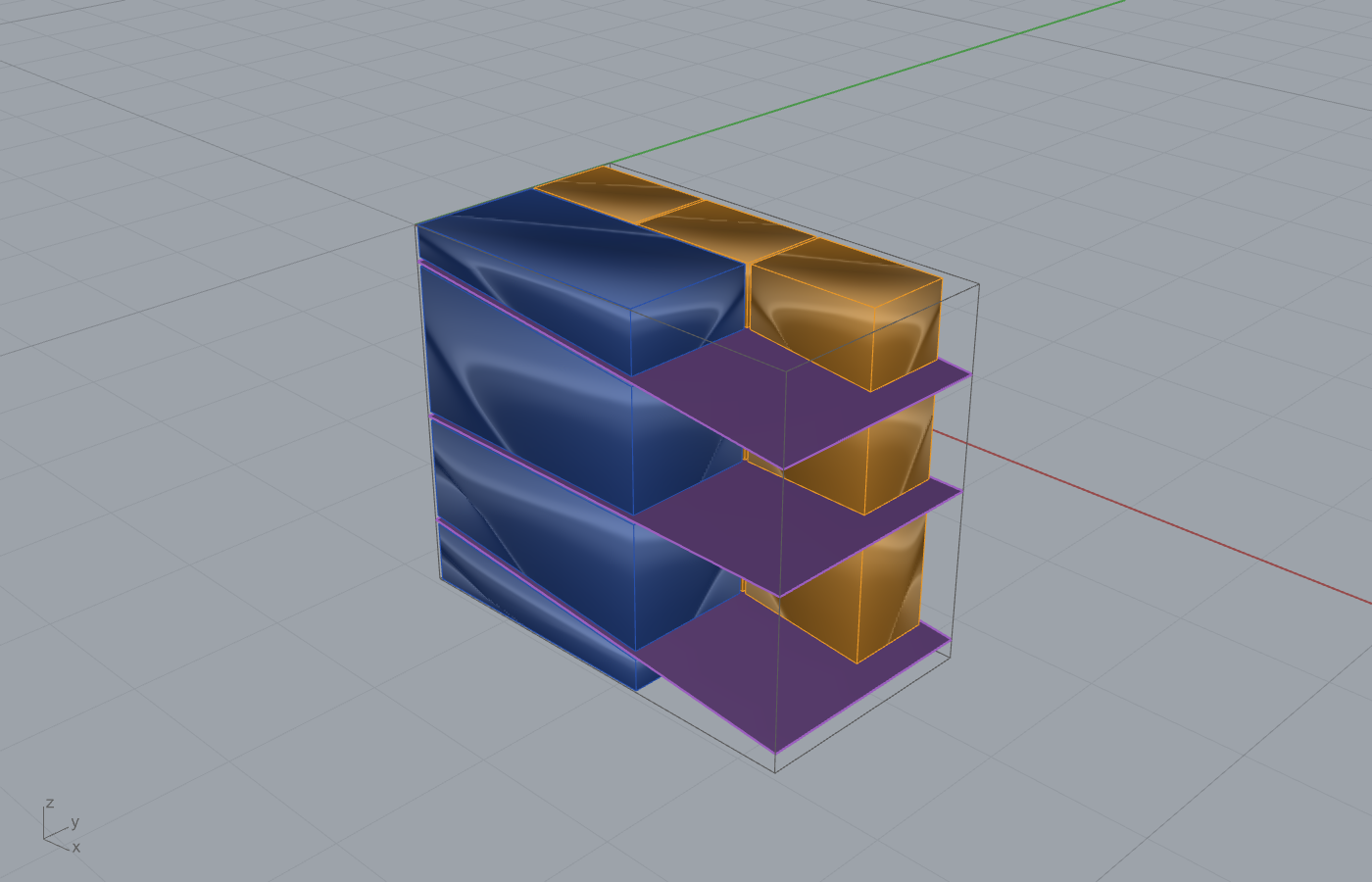
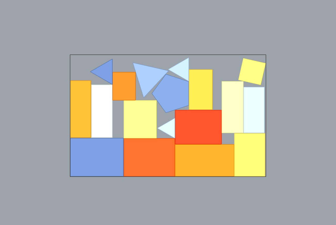
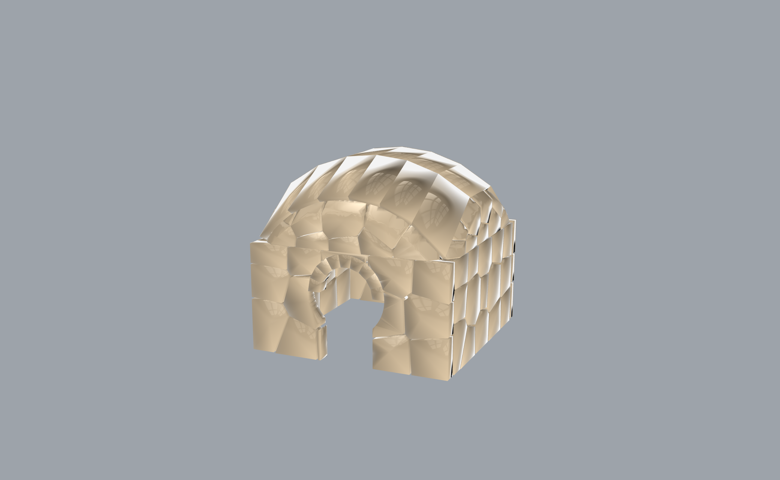
These are git-tracked example renders that exercise the spine across both design flows. Each is the visually validated form (criterion c), produced on the canvas, not by an external bake script.
Top-down cutting and yield (process → segment → pack/cut → fabricate):
2D and 3D packing (pack/cut):
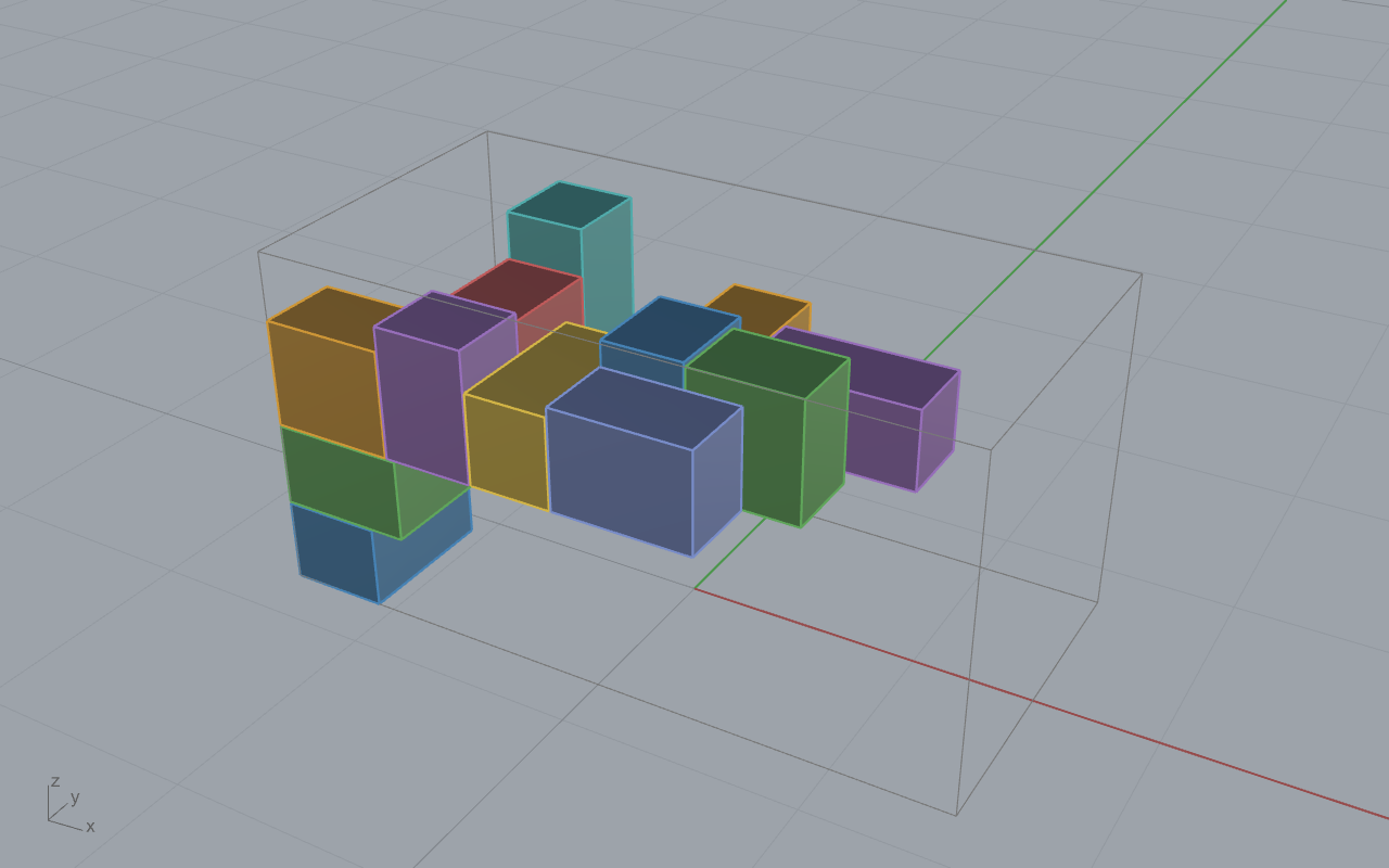
Bottom-up masonry assembly (segment → pack/cut → stabilise):
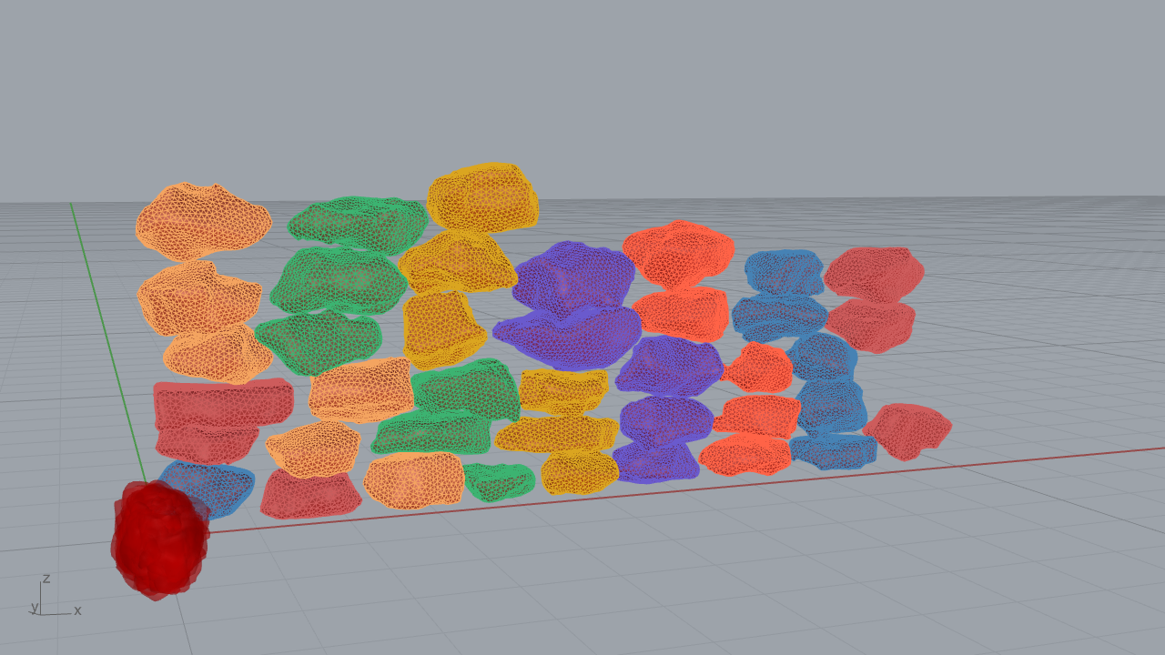
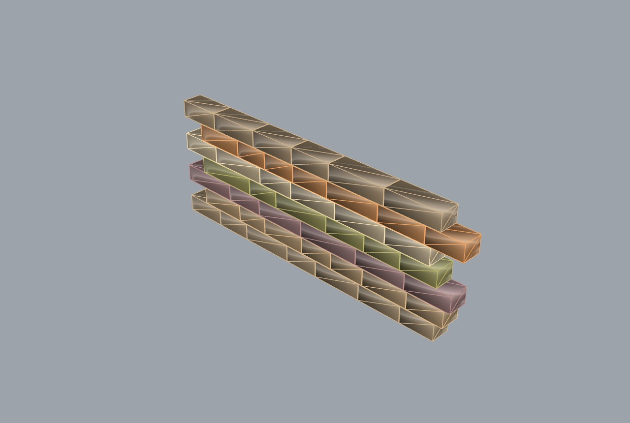
Polygonal masonry at building scale (top-down form, contact-stable):
References¶
- CGAL Polygon Mesh Processing. GPLv3 / commercial. https://doc.cgal.org/latest/Polygon_mesh_processing/
- Johnson, A. Clipper2. BSL-1.0. Vatti-derived polygon clipping. https://github.com/AngusJohnson/Clipper2
- Kazhdan, M., Bolitho, M. & Hoppe, H. (2006). Poisson surface reconstruction. Eurographics Symposium on Geometry Processing. (Bundled inside Geogram as
GEO::PoissonReconstruction.) - Lévy, B. Geogram v1.9.9. BSD-3. INRIA / ALICE. https://github.com/BrunoLevy/geogram
- Sawhney, R. & Crane, K. (2017). Boundary First Flattening. ACM Transactions on Graphics 36(4):109. DOI 10.1145/3072959.3056432.
01. Two-Dimensional Nesting & Trencadís¶
This chapter covers the repository's two-dimensional geometry-packing
subsystem: the 2D Packing ribbon tab (13 components) and the Trencadis
ribbon tab (5 components). The shared engine is exact No-Fit-Polygon
Bottom-Left-Fill on a Clipper2 integer-snapped back end. Three nesters are in
scope: the shipped IrregularSheetFillV506 (FreeNest), its exact-NFP sibling
IrregularSheetFillNfpBlf (FreeNestX), and the hole-aware
ContactNfpHoleNester / CNH (HoleNest). The Trencadís family adds a
centroidal-Voronoi cell partition plus optimal one-to-one shard assignment.
The mathematics here is real plane geometry: Minkowski sums, the no-fit and
inner-fit polygons, and a distance-based penetration certificate. Where the
repository evolved the published math we show the derivation, not only the
final formula. Every originality claim is anchored to a file:line, an
[Algorithm] attribute, or a measured benchmark.
The packing-quality metric used throughout is stock utilisation
placed part material area over net sheet area (sheet minus its holes). It is
computed by boolean area, not bounding boxes, and it is reported, not
gated in the components; the gate is the zero-overlap validity certificate
of section 1.6. (Definition: examples/10_pack2d/README.md.)
1. The No-Fit-Polygon nesting core¶
1.1 The no-fit polygon (NFP)¶
Let two polygons \(A\) and \(B\) be given with \(A\) fixed and \(B\) free to translate by \(t\in\mathbb{R}^2\). Write \(B(t)=\{b+t : b\in B\}\). The no-fit polygon is the set of translations for which the interiors of \(A\) and \(B\) overlap:
The standard result (Bennell and Oliveira 2009) is that this set is exactly a Minkowski sum of \(A\) with the point-reflection of \(B\):
Derivation. The interiors meet iff there exist \(a\in A\), \(b\in B\) with
\(a=b+t\), i.e. \(t=a-b=a+(-b)\). The set of all such \(t\) is exactly
\(\{a+(-b)\}=A\oplus(-B)\). Placing \(B\) at any \(t\) on the boundary of this set
makes \(A\) and \(B\) touch without interior overlap; any \(t\) outside the set is
collision-free. This is the geometric primitive every component in this
chapter uses for collision. In code the reflection is Reflect and the sum is
Clipper2Adapter.MinkowskiSum
(ContactNfpHoleNester.cs:1484, :962; the engine contract is documented at
ContactNfpHoleNester.cs:28-31).
1.2 The inner-fit polygon (IFP)¶
The container constraint is the dual. The inner-fit polygon is the set of translations that keep \(B\) inside a container \(C\):
For a convex container this is an erosion (Minkowski difference) \(C\ominus B\). The repository realises it as an exact intersection over the vertices of the convex hull of \(B\):
Derivation. \(B(t)\subseteq C\) holds iff every vertex \(b_i+t\in C\). Because
\(C\) is intersected against the convex hull of \(B\), containing the hull
vertices is sufficient to contain all of \(B\) (a convex combination of points
in a convex set stays in the set). Each constraint \(b_i+t\in C\) rearranges to
\(t\in C-b_i\), and the feasible \(t\) is the intersection over all hull vertices.
This is exact for a convex \(C\) and conservative (never admits an
out-of-bounds placement) for a concave \(C\) (ContactNfpHoleNester.cs:1332-1352;
hull by Andrew's monotone chain, :1355-1368). The hull pass is the
cost saver: it replaces a full-resolution erosion with at most
\(|\operatorname{hull}(B)|\) Clipper intersections.
1.3 The feasible region and Bottom-Left-Fill¶
Combining the two, the set of legal placements of part \(B\) at a fixed rotation, given a sheet \(S\) with holes \(\{H_l\}\) and already-placed parts \(\{A_k\}\), is
This is stated verbatim in the engine header
(IrregularSheetFillNfpBlf.cs:18-27) and in the CNH header
(ContactNfpHoleNester.cs:30-31). Non-overlap is therefore a hard
constraint of construction, not a post-hoc trim.
The Bottom-Left-Fill placement rule (Burke et al. 2006) selects, among all feasible translations, the one that is lowest, then leftmost:
The optimum of a linear lexicographic objective over a polygonal region lies at
a vertex of that region, so the search reduces to scanning the
feasible-region vertices in \((y,x)\) order and taking the first that survives
verification (ContactNfpHoleNester.cs:980-1002,
OrderedVertices :1625-1634; IrregularSheetFillNfpBlf.cs:314-315).
Originality. The NFP-BLF nesting family is clean-room. The published mathematics is cited in source by
[Algorithm]attributes: Bottom-Left-Fill to Burke, Hellier, Kendall, Whitwell (2006), Operations Research 54(3):587-601, DOI10.1287/opre.1060.0293; NFP/IFP via Minkowski sum to Bennell and Oliveira (2009), JORS 60(S1):S93-S105, DOI10.1057/jors.2008.169; the boolean back end is the vendored Clipper2 (Johnson, BSL-1.0) with no copyleft (evidence:IrregularSheetFillNfpBlfComponent.cs:24-32,HoleNestComponent.cs:25-33). No upstream nesting source sits in the tree. Tier B (faithful implementation of published work), with the V506 to NFP-BLF delta and the CNH increments below carrying the research weight.
1.4 V506 to NFP-BLF: the measured delta¶
The originally shipped nester is IrregularSheetFillV506 (FreeNest, GUID
D5E7A2B1-8C34-4F1E-A096-3B7F5D2E8A4C). It is an NFP-assisted bottom-left
placement that, by design, permits a bounded overlap controlled by a
Trim Tolerance and then boolean-trims the contact. With the default
Trim Tolerance of 0.1 it produces apparent overlaps; this is the documented
behaviour, not a fault (KB-6/KB-7; examples/10_pack2d/README.md).
IrregularSheetFillNfpBlf (FreeNestX, GUID
2d351646-2cb0-402a-bbd8-3950b5bb1fbc) re-derives the placement so that the
feasible region is the complete IFP-minus-NFP set, making zero overlap a
hard constraint. The measured improvement is recorded in source: a mean wasted
area cut of 53.9% against V506 at zero overlap, validated against a Python
reference (IrregularSheetFillNfpBlf.cs:21-22). FreeNestX is the only
zero-overlap packer in the study to cross the 80% utilisation bar with holes:
82.0% oversub, 84.7% on the L-plus-hole fixture, 89.6% on a hard 3-hole
fixture (examples/10_pack2d/README.md). The four legacy V1/V2/V3/V506
wrappers are marked [Obsolete] and Exposure=hidden per the 2D-V-solver
phase-out (Pack2DIrregularSheetV506Component.cs:56-57).
Originality. FreeNestX is an evolved-fork of V506: same NFP/BLF lineage, but a re-derived complete feasible region replaces the overlap-then-trim contract, with the 53.9% waste-cut measured delta (
IrregularSheetFillNfpBlf.cs:18-27, commit lineage atoutputs/2026-06-03/pack2d_nfp_evolution).Supersession note (2026-07-05): FreeNestX and the Unified dispatcher were subsequently hidden in the packer consolidation; the shipping nesters are
Sheet Nest (Hole-Aware)andSheet Nest (Live)on the singleContactNfpHoleNestercore. See the Post-completion addendum.
1.5 The Unified dispatcher¶
IrregularSheetFillComponent (FreeNestU, GUID
AB12C00B-1A2B-4C3D-9E4F-5A6B7C8D9E0B) is a strategy selector that dispatches
to the V1/V2/V3/V506 variants behind one canvas box. It adds no new algorithm;
every internal step resolves to an in-repo nesting variant.
Originality. facade-over-primitives (variant dispatcher), with the
[Algorithm]note explicitly calling it a "Frahan-original strategy selector" over Burke 2007 and Bennell and Oliveira 2008 (IrregularSheetFillComponent.cs:32-33,:42).
1.6 The hole-aware nester (CNH / ContactNfpHoleNester)¶
The ContactNfpHoleNester (HoleNest component, GUID
D5F10019-8A3C-4D17-B5E2-6C90F2A47D31) evolves FreeNestX with two capabilities
it lacks, both validated in outputs/2026-06-12/hole_packer_evolution
(ContactNfpHoleNester.cs:10-33).
1.6.1 Contact-adaptive rotations¶
A fixed rotation list cannot seat a part flush against a wall, a neighbour, or a hole edge. CNH augments the uniform base set \(\{0,\tfrac{\pi}{2},\pi,\tfrac{3\pi}{2}\}\) with edge-alignment angles. For a host edge with direction angle \(\alpha_h\) and a part edge with direction angle \(\alpha_p\), the rotation that makes the part edge parallel to the host edge is
evaluated over the longest edges of the part against the longest edges of the
sheet and the most recently placed neighbour (ContactNfpHoleNester.cs:1304-1330,
RotationSet :1281-1302). The total angle budget is bounded by
\(\max(4,\ \mathrm{base}+4+2\,\mathrm{contact})\), and symmetric rotations are
collapsed by a translation-invariant shape signature (RotSignature,
:1917-1929) so each distinct rotated shape evaluates its NFP once.
1.6.2 Part-in-part-hole nesting (holes-first)¶
A small part can be nested inside the hole of a larger placed part. The
hole acts as a container, so the legal translations of filler \(B\) into host
hole \(G\) are exactly the inner-fit region \(\mathrm{IFP}(B,G)\) of section 1.2.
The schedule is holes-first: parts that have holes are placed as hosts (area
descending), the smallest remaining parts are nested into the open host holes,
then the remaining outers are placed by NFP-BLF
(ContactNfpHoleNester.cs:528-592). This is the GPR-defect-as-sheet-hole
differentiator for stone: pack saw-cuttable parts only in intact rock,
nesting offcuts into the voids of larger remnants
(outputs/2026-06-12/hole_packer_evolution/HOLE_PACKER_MATH_AND_BENCHMARK.md,
section 4).
1.6.3 The penetration-depth certificate (original derivation)¶
The NFP and IFP are built on simplified inputs: a Ramer-Douglas-Peucker pass
with tolerance \(\tau=2\times10^{-3}\,\mathrm{diag}(p)\) carves the no-fit
region slightly inward (NfpSimplifyTol, :1619-1623), and the hull-based IFP
is anti-conservative on concave sheets. Area-relative gates alone admit
needle overlaps: a tiny intersection area (order \(10^{-5}\) of part area)
but a penetration depth up to roughly 0.2 caller units. The repository's answer
is a compound gate on the true, unsimplified geometry; the NFP/IFP are
treated as pruning devices only (ContactNfpHoleNester.cs:35-72).
For loops \(A\) and \(B\), penetration depth is the maximum distance any probe of one loop that lies strictly inside the other travels to that other loop's boundary, augmented by an edge-crossing term:
where the probe set \(\Pi(\cdot)\) is the loop's vertices, edge midpoints, and
area centroid (the centroid closes the full-containment blind spot), and
\(d_{\times}\) is the maximum proper edge-crossing perpendicular depth
(PenetrationDepth :1777-1798, DepthProbes :1822-1839,
MaxProperCross :1879-1908). Containment uses the analogous
OutsideDepth.
A candidate is accepted only if its depth stays under a scale-relative tolerance instantiating the project epsilon budget at the verification level:
with \(\mathrm{SnapGrid}=0.01\) scaled units \(=10^{-5}\) caller units at the
internal scale \(1000\) (DepthTolFor :1646-1647, constants :1640-1643).
Engine math runs in scaled space because Clipper snaps to a fixed decimal
precision; small-unit (metre) geometry would otherwise build sliver-noisy NFPs
(Pack conditioning :121-154).
The micro-retreat. Rather than discard a contact-tight candidate that only violates through NFP simplification, the gate nudges it once along the measured penetration vector \(\mathbf{p}=(p_x,p_y)\) (length \(=d\)) by \(d+\mathrm{SnapGrid}\) and re-verifies:
If the nudged placement passes, it is accepted; otherwise the candidate is
rejected (TryVerifiedCandidate :1728-1748). This keeps the layout from
starving while never accepting a deeper-than-floor penetration. The same
compound gate runs path-independently in Validate (:1373-1449), so
Valid==true certifies the layout on every engine path, including the
fast path below.
1.6.4 The rect shelf fast-path¶
When every loop in the instance is an axis-aligned rectangle, the NFP and IFP
degenerate to rectangles and the whole solve reduces to interval arithmetic
with no Clipper calls. Rotations collapse to \(\{0,\tfrac{\pi}{2}\}\) (squares to
\(\{0\}\)) using the exact integer map \((x,y)\mapsto(-y,x)\) so there is no
trigonometric round-off (TryRectFastPath :635-738, detection :742-767,
exact transform :883-895). A completeness fallback guards it: if the
sparser shelf candidate set strands any part (about 1 in 4000 in fuzzing), the
fast-path result is discarded and the general engine runs, so speed never
trades away a placement (Pack :173-189).
1.6.5 Multi-start keep-best¶
The general engine optionally runs \(K\) deterministic part orders (area,
max-dimension, width, height; all descending) and keeps the densest valid
layout, breaking ties by placed count, then density, then smallest used
bounding-box diagonal (BuildOrder :424-438, keep-best :243-292). The
ordering keys form a total permutation, so the winner is reproducible.
Determinism is enforced at the cache level: each pass allocates its own
NFP cache keyed on (obstacle index, rotation signature), and the index is into
the per-pass placement order, so a cache shared across passes would return the
wrong NFP. The header documents this as the critical correctness point
(ContactNfpHoleNester.cs:199-210). \(K=1\) reproduces the original single pass
byte-for-byte; FRAHAN_MULTISTART=0 is the kill switch.
1.6.6 Deviation-compensated spacing (original derivation)¶
The solver collides on sampled proxies of smooth curves, but the output is
the exact original curve. A chord cuts inside the true curve by the sampling
sagitta, so two proxies that merely touch can let the true full-resolution
curves cross by up to that deviation on each side. The Grasshopper wrapper
measures the worst proxy deviation (max distance from a chord midpoint back to
the true curve) and inflates the engine spacing to compensate
(HoleNestComponent.cs:758-790, :532-542):
Derivation of the asymmetric coefficients. A part-to-part clearance must
absorb the deviation of both colliding part proxies, hence \(2\delta_{\text{part}}\).
A part-to-sheet clearance absorbs the part deviation through the same term, but
the sheet term enters once: a part can poke past the true boundary by at
most the sheet proxy's own deviation, and the sheet samples at high resolution
(192 verts) so \(\delta_{\text{sheet}}\) stays tiny. The earlier shared formula
used \(2\,\max_{\text{all loops}}\delta\), which let a large freeform sheet's
deviation inflate every part (a reported +27 units on the user's S-sheet,
collapsing a fill from 200 to 21); the asymmetric split is the fix
(HoleNestComponent.cs:45-48, :532-542). The compensation is surfaced to the
user as ProxyDevComp: +{2*maxDev} in the report (:653).
Originality. CNH is clean-room at its NFP/BLF/IFP base (same citations as FreeNestX,
HoleNestComponent.cs:25-33) with three evolved-fork increments that carry the research weight, each measured or fuzz-verified: the contact-adaptive rotation set, the part-in-part-hole IFP nesting, and the distance-based penetration certificate with micro-retreat. The[Algorithm]attribute names these as "Frahan ContactNfpHoleNester evolution study" and the head-to-head protocol is documented, not asserted (HoleNestComponent.cs:34-36). The component is the CNH facade over the Core engine. The native batched-NFP path wrapsnfp_kernel.dll, which vendors official Clipper2 (BSL-1.0) unmodified (NativeNfpKernel.cs:10-22); that is vendored-library, with only the marshalling ours.
1.6.7 Head-to-head: V506 vs NFP-BLF vs CNH vs the reference physics nester¶
The 2026-06-12 hole-packer study benchmarked CNH against the OpenNest-lineage
reference physics nester (the jagua-rs guided-local-search strip packer,
"Sparrow") and an MIT-licensed C++ NFP-GLS native nester
(HOLE_PACKER_MATH_AND_BENCHMARK.md). On the true-hole lane (1 sheet, 1
sheet-hole, 4 host parts with slanted holes, 8 fillers):
| Packer | time | placed | holes filled | valid | deterministic |
|---|---|---|---|---|---|
| CNH v1 (general exact-NFP) | 60.7 ms | 12/12 | 4 | true | yes |
| CNH v2 (rect fast-path) | 0.148 ms | 12/12 | 4 | true | yes |
| MIT native nester (shelf) | 21.6 ms | 12/12 | 4 | true | no (stochastic) |
| Reference physics nester (Sparrow) | 3255 ms | 12/12 outlines | 0 | false | no |
CNH is valid where the reference physics nester is invalid: Sparrow ignores
holes (4 hole-ignore warnings, 953.7 overlap loss) and produces no usable
hole-aware layout at any time budget. Against Sparrow, CNH v1 is about
54x faster and valid on the same parts (60.7 ms vs Sparrow's invalid 3255 ms);
the rect fast-path is 0.148 ms, about 22,000x the invalid Sparrow time. Against the
strongest valid baseline (the native shelf) CNH v1 is 2.8x slower because it runs
the general exact-NFP construction rather than an axis-aligned shortcut; its v2 rect
fast-path runs in 0.148 ms on the true-hole bench, 146x the native shelf's 21.6 ms on
that same instance (an axis-aligned shortcut, not a separate all-rectangle benchmark),
and it is the only deterministic engine.
The honesty boundary is held in source: on the outline-only strip lane the
reference physics nester still wins density by 6 to 10 percent, and no
universal "2x better" claim is made there
(docs/benchmarks/HOLE_PACKER_MATH_AND_BENCHMARK.md, sections 2-3).
2. Trencadís mosaics¶
Trencadís is the Gaudí "broken-tile" technique: irregular shards placed close
together with a grout gap. The repository ships two distinct solver
philosophies under the Trencadis tab, plus an EdgeMatch variant.
2.1 Catalog mode: CVD-Lloyd cells + Hungarian assignment¶
Pack2DTrencadisCatalogComponent (TrencadisCat, GUID
F2D00007-CADC-4F2D-9007-7E60CADA15A0) is the example-12 engine. It partitions
the sheet into blue-noise cells then assigns shards to cells one-to-one.
Centroidal Voronoi cells (Lloyd 1982). A Voronoi diagram of \(K\) seeds is centroidal when each seed coincides with the centroid of its own cell. Lloyd's algorithm reaches this fixed point by iterated relaxation: assign each domain point to its nearest seed, then move each seed to the centroid of its cell:
The repository discretises the domain (outer polygon minus holes) on an
\(N\times N\) grid with uniform density \(\rho\equiv 1\), assigns each grid cell to
its nearest seed, recentres, and stops when the largest seed move drops below
half a grid step (CvdLloyd2d.cs:30-108). The result is a blue-noise seed
field, far better than placing the first piece at a bbox corner.
Optimal assignment (Kuhn-Munkres). With \(n\) shards and \(n\) cells, let the cost \(c_{ij}\) be the area mismatch of placing shard \(i\) in cell \(j\). The minimising one-to-one assignment solves
via the \(O(n^3)\) shortest-augmenting-path Hungarian method, with row and
column potentials \(u_i,v_j\) maintained so reduced costs
\(c_{ij}-u_i-v_j\ge 0\) stay non-negative (HungarianAssignment.cs:23-85). Each
placed shard is moved to its cell centroid and inset by the grout offset to
leave the mortar gap. Example 12 places 28 shards into 28 cells in 53 ms with
zero warnings (examples/12_trencadis/README.md).
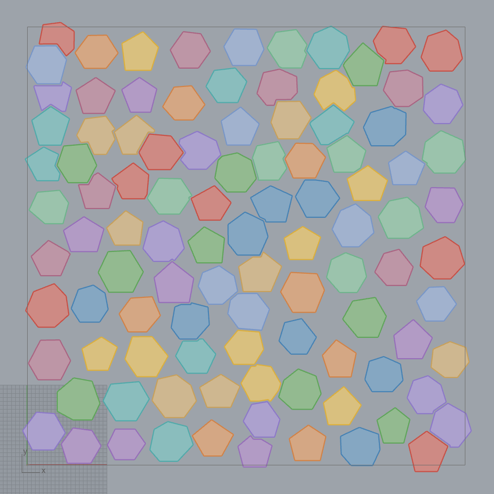
Originality. CVD-Lloyd is clean-room from Lloyd (1982) centroidal Voronoi relaxation (
CvdLloyd2d.cs:14-22,[Algorithm]atPack2DTrencadisCatalogComponent.cs:37). The Hungarian solver is a clean-room textbook Kuhn-Munkres / Bourgeois-Lassalle (1971) shortest-augmenting-path implementation, allocation-bounded and net48-compatible (HungarianAssignment.cs:11-15). The catalog placement wrapper that couples them is facade-over-primitives: its[Algorithm]credits "Slab-partitioned Voronoi catalog; Frahan-original Trencadis extension" over a Battiato 2013 synthesis precedent (Pack2DTrencadisCatalogComponent.cs:38,:42). Tier C/B.
2.2 Physics-settle variants vs the greedy/EdgeMatch variants¶
The Trencadis tab is intentionally not one engine. The variants differ in
how a piece reaches its final pose, and the repository keeps them separate
rather than blind-merging them (the "the 2D solvers are real, validate don't
merge" ruling):
- Greedy NFP-slide (
Pack2DTrencadisComponent, GUIDF2D00002-...). Pieces slide along a Minkowski-difference arc-length sampler until they butt against placed neighbours, with a bounded-overlap trim up to the Trim Tolerance and the Battiato 2013 §4 cumulative-cut budget (\(T_N\) for the new piece, \(T_P\) for placed) (TrencadisFill.cs:13-27,Pack2DTrencadisComponent.cs:37-38). The standalone greedy box is a skeleton returning empty; the working entrypoint is the catalog or pipeline component (examples/12_trencadis/README.md). - Dynamic settle (
Pack2DTrencadisDynamicComponent, GUIDF2D00008-...). After a greedy pack, a Kangaroo 2 goal-based dynamic relaxation pass settles the pieces to fill residual gaps (physics, not geometry). Headless coverage 55.1% with physics on vs 52.7% greedy (Pack2DTrencadisDynamicComponent.cs:61-62,examples/12_trencadis/README.md). - EdgeMatch (
TrencadisEdgeMatchComponent, GUIDF2D0000A-...). Drives placement through the 5-stage EdgeMatch pipeline plus a deterministic beam-search assembly solver, an alternative to the Battiato 2013 CVD+GVF stack (TrencadisEdgeMatchComponent.cs:28-29). - Pipeline (
Pack2DTrencadisPipelineComponent, GUIDF2D00009-...) composes greedy pack + NFP slide + CVD-Lloyd seeding + an optional Kangaroo 2 settle (Pack2DTrencadisPipelineComponent.cs:59-62).
Originality. The greedy NFP-slide and the dynamic/EdgeMatch/pipeline wrappers are facade-over-primitives that compose published Frahan primitives (CVD-Lloyd, NFP slide, Hungarian, EdgeMatch, the Kangaroo 2 relaxation). The physics step explicitly credits Daniel Piker's Kangaroo 2 (
Pack2DTrencadisDynamicComponent.cs:62); the Trencadís domain framing is credited to Gaudí Park Güell and the Battiato 2013 synthesis. None claims a new algorithm; the contribution is the integration. Tier C/D.
3. Status & what's left¶
- Example 28 (hole nest) has no rendered figure. The folder ships the
.ghdemo only (examples/28_hole_nest/), no PNG and no README. The CNH renders in this chapter borrow from example 10 (nesting) and example 12 (Trencadís). Severity: low (documentation gap, not a code gap). - Deployed
.ghalag (KB-7). The example-10 validity figures are from the headless harness on current source. An older deployed.ghamay still overlap parts on a live 2D solve; rebuild and redeploy before trusting a live result (examples/10_pack2d/README.md). Severity: medium. - Standalone greedy Trencadís box returns empty.
Frahan Trencadís Packis a skeleton; the working entrypoints are the Catalog and Pipeline components (examples/12_trencadis/README.md). Severity: medium (a ghost on the ribbon, against AGENTS.md section 6). - Rect fast-path spacing limitation. The exact rectangle shelf path only
activates at
spacing == 0; spacing > 0 needs exact rect-dilation bookkeeping and is deferred to the general engine (ContactNfpHoleNester.cs:611-616). Severity: low (correct fallback exists). - Residual penetration band. After the compound gate, penetrations inside
the snap band (about \(2\times10^{-5}\) caller units) can be accepted; deeper
ones cannot on any path. This is a stated, bounded residual, far inside any
fabrication budget (
ContactNfpHoleNester.cs:69-72). Severity: low. - Outline-density gap to the reference physics nester. On the no-hole
outline strip lane the reference physics nester (Sparrow) still wins density
by 6 to 10 percent; CNH's claimed win is the hole-aware lane only. This
boundary must stay in any external claim
(
HOLE_PACKER_MATH_AND_BENCHMARK.md, section 2c). Severity: low (honesty, not a defect).
References (this chapter)¶
- Burke, E.K., Hellier, R., Kendall, G., Whitwell, G. (2006). A New Bottom-Left-Fill Heuristic Algorithm for the Two-Dimensional Irregular Packing Problem. Operations Research 54(3):587-601. DOI 10.1287/opre.1060.0293.
- Burke, E.K., Hellier, R., Kendall, G., Whitwell, G. (2007). Complete and robust no-fit polygon generation for the irregular stock cutting problem. European Journal of Operational Research 179(1):27-49. DOI 10.1016/j.ejor.2006.03.011.
- Bennell, J.A., Oliveira, J.F. (2009). A tutorial in irregular shape packing problems. Journal of the Operational Research Society 60(S1):S93-S105. DOI 10.1057/jors.2008.169.
- Lloyd, S.P. (1982). Least squares quantization in PCM. IEEE Transactions on Information Theory 28(2):129-137. DOI 10.1109/TIT.1982.1056489.
- Kuhn, H.W. (1955). The Hungarian method for the assignment problem. Naval Research Logistics Quarterly 2(1-2):83-97. DOI 10.1002/nav.3800020109.
- Battiato, S., Di Blasi, G., Gallo, G., Guarnera, G.C., Puglisi, G. (2013). Artificial mosaic generation: a survey and synthesis. (Trencadís synthesis precedent, cited in source.)
- Johnson, A. Clipper2 (Boost Software License 1.0). Polygon Minkowski sum and NonZero boolean back end.
02. Three-Dimensional Packing & Settling¶
This chapter covers the repository's volumetric packing subsystem: the
3D Packing ribbon tab (9 components) and the Slab ribbon tab (4
components). Three distinct engine families live here. The first is a family of
heightmap packers (a flat-bed greedy box packer, a mesh-derived top/bottom
pile packer, and an irregular mesh-container variant) that place geometry by a
deepest-bottom-left rule on a discrete grid. The second is the guillotine /
DLBF layer: the Block Pack (Tree) forest packer and the HeteroExt
mixed-size extraction facade that share a single deepest-left-bottom-fill (DLBF)
engine across timber, ceramic, and concrete catalogues. The third is the
physics settle layer: a Bullet rigid-body service that turns a proxy
placement into a settled pile of real geometry. The Slab tab adds convex
half-space slab cutting by oriented fracture planes.
The repository's own research arc runs straight through this chapter. The
shipped baseline was a heightmap proxy packer; the evolution study replaced it
with a mesh-accurate collision plus drop-settle pipeline that roughly doubles
packing compactness on the ETH1100 dry-stone benchmark while producing a stable,
non-interpenetrating pile (section 2.4). Where the repository evolved the
published math, the derivation is shown. Every originality claim is anchored to
a file:line, an [Algorithm] attribute, or a measured benchmark.
The packing-quality metrics used throughout are the fill ratio
(placed item volume over container volume; PackingMetrics.cs:43-45) and the
evolution-study compactness
packed true mesh volume over the swept footprint column (floor area times used
height), which rewards interlocking rather than bounding-box stacking
(outputs/2026-06-03/pack3d_evolution/PLAN.md, section 5).
2.1 The heightmap deepest-bottom-left core¶
2.1.1 The flat-bed box heightmap¶
The simplest packer fills an axis-aligned box container with axis-aligned item
boxes. A Heightmap stores one scalar per grid cell: the current top surface
\(T(x,y)\), the maximum \(z\) already occupied at that cell (Heightmap.cs:8,
:28). To place an item of footprint \(w\times d\) at grid cell \((i,j)\), the
landing height is the highest top under the item's footprint,
with \(c\) the cell size, and the placement is legal only if it stays under the
container ceiling, \(z+h\le H+\varepsilon\) (Heightmap.cs:30-50). Placement is a
greedy argmin over a score that trades vertical growth against a
back-left compactness bias:
the first term being the new material lifted above the existing surface (low is
flush), the second a lexicographic-style pull toward the origin corner
(Heightmap.cs:52-69). The GreedyHeightmapPacker sorts items by volume
descending, evaluates each over \(\{0^\circ,90^\circ\}\) yaw, and commits the
lowest-score candidate, bounded by a MaxCandidatesPerItem budget
(GreedyHeightmapPacker.cs:17-19, :44-82). The argmin is exact over the
evaluated candidate set; there is no overlap by construction because the
heightmap is monotone.
This is a textbook deepest-bottom-left / skyline heuristic. The relevant
published anchor is the deepest-left-bottom-fill (DLBF) algorithm of Chehrazad,
Roose and Wauters (2025), which the components cite as the substrate
(Pack3DIrregularComponent.cs:20-23).
2.1.2 The mesh-pile heightmap (top and bottom surfaces)¶
A box top-surface heightmap cannot nest a concave stone into the dimple of the
stone below it: it only knows the highest point of each column, so it stacks
flat tops on flat tops. The OrientedMeshHeightmap fixes this by rasterising
two surfaces per cell from the item's triangle mesh: a bottom envelope
\(b(x,y)\) and a top envelope \(t(x,y)\) (OrientedMeshHeightmap.cs:8-10,
:276-292). Each triangle is scan-converted by barycentric interpolation over
its footprint cells, and vertices, edge samples and the centroid are added so
thin or degenerate triangles still deposit samples (:195-244). The cell stores
the per-column min as the bottom and the per-column max as the top.
The MeshPileHeightmap then seats one mesh into another. For a candidate at
grid offset \((i,j)\), the landing height is chosen so the item's bottom envelope
rests on the pile's current top surface at every occupied column:
so the deepest finger of the item drops exactly onto the highest point beneath
it (MeshPileHeightmap.cs:79-106). Unlike the box heightmap, the pile keeps a
list of occupied vertical intervals per cell, not just a top scalar, so a
later piece can slide under an overhang. A candidate is rejected if its
\([z+b,\,z+t]\) interval at any column overlaps an existing interval there:
a conservative vertical-column non-penetration test on the true mesh envelopes
(MeshPileHeightmap.cs:248-271). This is the "conservative vertical-column
collision check" the component name advertises.
2.1.3 Orientation and the down-axis rotation¶
The GreedyMeshHeightmapPacker searches up to six discrete orientations per
item: each of the three local axes tilted down to \(-Z\) (None / X-down / Y-down)
crossed with \(\{0^\circ,90^\circ\}\) yaw, with the \(90^\circ\) skipped when the
rotated footprint is square (GreedyMeshHeightmapPacker.cs:142-169). The down
rotation is applied to the vertices before the yaw, matching the world
transform order \(R_{\text{yaw}}R_{\text{down}}\). For the None case the down step
is a literal identity, so the multi-orientation engine is byte-identical to the
legacy yaw-only code on that path (OrientedMeshHeightmap.cs:115-152); the
Grasshopper transform reproduces the same order, \(T_{\text{yaw}}\cdot
T_{\text{down}}\), so the placed mesh matches the heightmap that scored it
(Pack3DMeshHeightmapComponent.cs:269-301).
2.1.4 The irregular mesh container¶
A real container is not a box. IrregularMeshContainer.FromMesh ray-casts a
vertical line through the cell centre of every grid cell, collects the sorted
\(z\) values where the line crosses a container triangle, and pairs consecutive
crossings into solid intervals (IrregularMeshContainer.cs:52-97,
:133-176). The crossing-parity pairing \(\{z_0,z_1\},\{z_2,z_3\},\dots\) is the
standard ray / closed-surface inside test: an even number of crossings bounds
the interior segments. Cells with fewer than two crossings are outside the
container and marked not-allowed. The pile packer then honours those per-cell
allowed intervals, raising a candidate's \(z\) until the item fits inside a
container interval or rejecting it (MeshPileHeightmap.cs:160-246). A
surface-sample fallback handles meshes that produce no closed columns
(IrregularMeshContainer.cs:99-131).
Originality. The heightmap packers are clean-room. The deepest- bottom-left placement rule and the DLBF substrate are cited to Chehrazad, Roose and Wauters (2025) (
Pack3DIrregularComponent.cs:20-23; GUIDE36C3F7D-7E2C-495E-9E2A-59312C5CF990). The two-surface mesh-pile proxy, the per-cell vertical-interval collision test, the six-orientation down-axis search and the ray-cast irregular container are Frahan additions over a box skyline; the mesh-heightmap component labels its method "Frahan-original mesh-pile heightmap" (Pack3DMeshHeightmapComponent.cs:20-21; GUIDA16D6426-38A8-44B1-AB6A-4BA80EB39730). No upstream packing source sits in the tree. Citation flag: the sibling container component attributes the same heightmap method to "Park and Han 2024 tree-packing" (Pack3DIrregularContainerComponent.cs:18,:22); that work (references[R8]) carries no DOI and is a placeholder-grade citation, while the mesh-pile component calls the identical method Frahan-original. The two attributions should be reconciled before external review (AGENTS.md §9).
2.2 The guillotine forest packer: Block Pack (Tree)¶
BlockPackTreeComponent (GUID C2D3E4F5-3001-4F5E-A6B7-C8D9E0F12345) packs a
set of element cuboids into a set of stone-block containers using only
axis-aligned, saw-cuttable guillotine cuts (BlockPackTreeComponent.cs:37).
It is the digital-fabrication entrypoint: every placement it returns is
reachable by straight saw passes, so the plan runs directly on a wire or bridge
saw (examples/11_pack3d/README.md).
A guillotine partition of a cuboid container is a binary tree: each internal node is one axis-aligned cut that splits a free region into two children; each leaf is either a placed element or free residue. The forest packer grows many such trees under independently seeded randomness and keeps the best by score. The Kim (2025) score sums packed element value with an all-fit container-price bonus,
where the final term is the Frahan / Jalalian I11 (BCSdbBV) extension that
charges for internal cutting-surface area \(A_{\text{internal}}\), so the packer
can be biased toward fewer, cheaper cuts (BlockPackTreeComponent.cs:30-31,
:154-158, :102-106). The component adds three documented capabilities
beyond the paper: a deterministic master seed (forest \(k\) uses \(\text{seed}+k\),
so parallel forests are bitwise identical to serial), a saw kerf width that
each cut consumes along its direction, and per-container forbidden boxes so
fracture-intersected cells can be passed in as keep-out regions
(BlockPackTreeComponent.cs:22-28). The measured live result on example 11 is a
full pack, 12/12 elements into one container, score 65.11, deterministic at
seed 0 (examples/11_pack3d/README.md).
Originality. evolved-fork of Kim (2025) (Computation 13:211, CC BY 4.0). The tree-forest growth and score are the paper's; the deterministic seed, kerf, forbidden-box, parallel-forest and memory-budget inputs are the stated deltas, and the cut-surface-area term cites Jalalian et al. (2023) (
[Algorithm]BlockPackTreeComponent.cs:30-31; synthesis inwiki/papers/kim2025_tree_packing.md). CC BY 4.0 is permissive with attribution, no copyleft. It sits on the Masonry ribbon by design to keep the recommended 11-panel layout intact (:13-21).
2.3 The DLBF mixed packer and the HeteroExt facade¶
2.3.1 The 3D deepest-left-bottom-fill engine¶
Dlbf3dMixedSizePacker is the 3D generalisation of the planar DLBF
(Dlbf3dMixedSizePacker.cs:8-37). It packs a multi-size catalogue, each entry
carrying its own per-piece height and per-piece revenue, into a tested AABB on a
discrete cubic grid. Pieces are processed in revenue-per-volume descending
order,
and for each piece the chosen cell is the deepest-left-bottom free cell in the strict order lowest \(z\), then lowest \(y\), then lowest \(x\):
scanning \(k\) as the outermost loop so the bench floor fills first
(Dlbf3dMixedSizePacker.cs:186-220). A region is free only if every cubic cell
it spans is unblocked, where blocked cells come from forbidden boxes (e.g.
fracture-intersected regions) rasterised into the grid (:166-184, :268-278).
Two operating modes split the use cases: FloorOnly = true clamps every piece
to \(z=z_{\min}\) for monoliths cut out of solid rock (no stacking), while
FloorOnly = false allows full 3D stacking for racking and container loading
(:24-29, kStop at :215). A 2026-06-06 evolution adds optional
best-of-orientation: each piece is tried in its up-to-six distinct
axis-permutations and placed in the orientation whose best free cell is lowest;
volume and revenue are permutation-invariant, and the default overload keeps
tryOrientations = false so the six existing tests stay byte-identical
(:127-143, :201-231, :250-266).
The outer while (anyPlaced) loop re-passes the catalogue until no further
piece fits, so a multi-instance catalogue packs greedily to exhaustion
(:194-245).
2.3.2 The HeteroExt facade: one engine, three materials¶
FrahanHeterogeneousExtractionComponent (HeteroExt, GUID
F2D0BC19-1234-4F2D-A0B0-7E60CADA15B9) is a four-stage extraction pipeline:
BlockCutOpt locates the fracture-clean regions of a bench, the 3D DLBF packer
fills those regions with a mixed catalogue of monuments, dimension stones and
slabs while avoiding the fractured cells, and an optional monument-inventory
stage places found stones on a fracture-derived block graph
(BlockCutOptHeterogeneousComponents.cs:169). The same Dlbf3dMixedSizePacker
that HeteroExt composes is also exposed standalone as Frahan Mixed-Size Block
Pack 3D (GUID F2D0BC18), satisfying the monster-vs-primitive rule that a
monolith must be a facade over a published, standalone primitive, never a black
box (:170-176, [RelatedComponent] cross-links). Because the engine packs a
revenue-weighted multi-size catalogue, it is the same mixed packer for timber,
ceramic and concrete instances; only the catalogue changes.
Originality. The DLBF 3D engine is clean-room from Chehrazad, Roose and Wauters (2025), following the paper's Section 5 generalisation; the standalone exposure carries the citation with DOI (
[Algorithm]BlockCutOptHeterogeneousComponents.cs:42, DOI 10.1080/00207543.2025.2478434). The HeteroExt monolith is facade-over-primitives: its[Algorithm]is "Frahan-original" with the explicit note that it composes Elkarmoty (2020) and Chehrazad (2025), both reimplemented in managed code, and that "the composition and the heterogeneity model are the contribution" (:169). No new algorithm; the integration and the seam-exposed standalone primitives are the work.
2.4 The physics settle: Bullet rigid-body¶
2.4.1 From proxy placement to settled geometry¶
A heightmap or DLBF placement is a proxy: it positions bounding-box or
height-column approximations, not the real stone in real contact.
Settle 3D (Physics) (PackSettle3DComponent, GUID
134785ac-19cb-4f14-85f8-e2f666bd14f6) is the finishing pass that composes
after any 3D packer and settles the meshes into a stable,
non-interpenetrating pile under gravity and friction
(PackSettle3DComponent.cs:16-28). Each stone is convex-decomposed (CoACD, with
a convex-hull fallback) into pieces wrapped as ConvexHullShape children of a
per-stone CompoundShape; bodies are seeded at their already-placed positions,
lifted slightly to clear convex-proxy overlap, then dropped
(BulletSettleService.cs:9-30, :111-133).
The settle is governed by Newton-Euler rigid-body dynamics integrated by
Bullet's sequential-impulse solver. The contact model is Coulomb friction with
a default coefficient \(\mu=0.85\) (SettleOptions.Friction,
BulletSettleService.cs:52). The load-bearing implementation detail is a
gravity ramp: seeded near-contacts are resolved softly by stepping
\(g_z\) through \(-0.5,-2.0,-5.0\) to full \(-9.81\) before the main settle loop, so
the pile does not explode from convex-proxy interpenetration at \(t=0\) (the
lesson recorded from the dev run; :135-141). Optional tamp rounds then apply
strong-gravity bursts to densify (:142-148). The component is heavy and
single-threaded, so it runs on a Run-gated background Task
(GH_TaskCapableComponent), never on the Grasshopper UI thread
(PackSettle3DComponent.cs:82-101).
The returned per-stone rigid delta is decoded carefully: Bullet stores its basis
row-wise for row-vector math, so the column-vector rotation applied to the mesh
is its transpose, and the world update is \(v'=R\,(v-\mathbf{c})+\mathbf{t}\) about
the piece centroid \(\mathbf{c}\) (BulletSettleService.cs:62-70, :152-164).
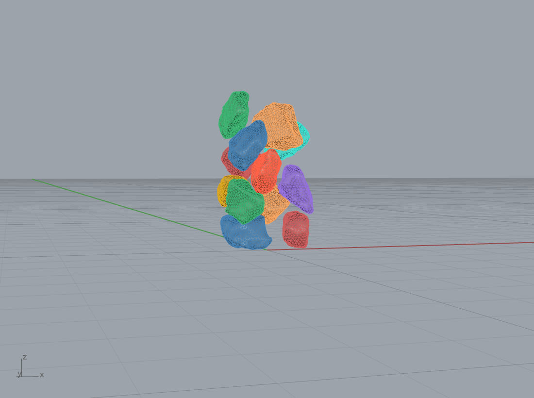
Example 18 settles 12 ETH1100 dry-stone scans into a roughly 1.95 m cluster
(examples/18_pack_settle_bullet/README.md).
2.4.2 COM-over-support stability (Heyman limit state)¶
Stability is the Heyman (1966) limit-state criterion shared with the masonry chapter: a settled stone is stable when its centre of mass, projected down to the bed, lies inside the convex hull of its contact footprint. Writing the support polygon \(\mathcal{S}=\mathrm{hull}\{\mathbf{p}_k\}\) over the contact points \(\mathbf{p}_k\), the gate is
so the resultant of self-weight passes through the support and no overturning
moment is unbalanced ([Algorithm] PackSettle3DComponent.cs:34-35). The
physics solver enforces this dynamically: a stone whose COM falls outside its
support topples and re-settles until it rests, which is exactly the equilibrium
the limit-state test certifies.
2.4.3 The heightmap-to-settle evolution (measured 2x)¶
The evolution study set the baseline as the shipping heightmap packer (GUID
B3E8A42F) and targeted a 2x improvement in wasted true-volume fraction at
zero interpenetration and full COM-over-support stability
(outputs/2026-06-03/pack3d_evolution/PLAN.md, sections 1, 3, 5). The measured
arc on the metric of section 2 is: v1 AABB greedy reached 17.0% compactness and
placed 19 of 30 stones; the mesh-accurate plus drop-settle v2 reached 33.2%
compactness, placed 30 of 30, and held 80% of stones COM-stable, rising to 100%
COM-stable with the stability-seat pass (PLAN.md, section 5). The
near-doubling of compactness from 17.0% to 33.2%, on real geometry and at full
placement, is the recorded heightmap-to-mesh-accurate-plus-settle 2x. The
heightmap path is retained as the validated baseline (the components route users
to Settle 3D and Block Pack (Tree) as the evolved paths;
Pack3DMeshHeightmapComponent.cs:12-15).
Originality. The settle service is clean-room physics integration over a vendored engine. The rigid-body dynamics packing framing cites Zhuang et al. (2024) (DOI 10.1016/j.cag.2024.103996); the engine is Bullet (Coumans et al.) via BulletSharp under zlib, and the convex pieces come from CoACD (Wei et al. 2022) (
[Algorithm]PackSettle3DComponent.cs:29-35). Bullet and BulletSharp are vendored unmodified (zlib, permissive); only the marshalling, the gravity-ramp seeding schedule and the centroid-relative transform decode are ours. The COM-over-support gate is Heyman (1966). CoACD is MIT but transitively vendors CGAL (GPL); per the licensing register it is reached only through the optional out-of-process shim with a convex-hull fallback, so the default install links no copyleft (docs/thesis/90_originality.md, register row 5).
2.5 The Slab tab: convex fracture cutting¶
The Slab tab turns a quarry block into fabricable slabs by cutting it along
oriented fracture planes. SlabFromMesh (GUID
B1A2C3D4-5E6F-4789-9ABC-1D2E3F4A5B6C) wraps a Rhino mesh into the internal
Slab DTO. SlabCutByFractures (GUID
C2B3D4E5-6F7A-489B-AC1D-2E3F4A5B6C7D) splits a list of slabs by a list of
planes (SlabCutByFracturesComponent.cs:44-60). Each plane, given as origin and
normal, classifies every slab vertex by signed distance \(d=\mathbf{n}\cdot
(\mathbf{v}-\mathbf{o})\) into above / on / below up to a tolerance \(\varepsilon\);
each face is walked once, and every directed edge that strictly straddles
contributes a linearly interpolated intersection point to both half-faces. The
cut cap is reconstructed by sorting the unique on-plane and intersection
vertices CCW about \(+\mathbf{n}\) in an in-plane 2D frame
(SlabCutter.cs:7-34). Cutting a slab by \(m\) ordered planes grows the piece
list by up to \(2\times\) per plane, since each plane splits every existing piece
(:55-70).
The managed path is exact for convex input only; non-convex slabs can
produce non-simple caps, so the component exposes an opt-in Use CGAL backend
that routes the cut through the corefinement boolean kernel for robust
non-convex or large-slab cutting, with a managed fallback if the CGAL shim is
absent (SlabCutByFracturesComponent.cs:84-92). The two further Slab-tab
members are Slab Cut By Tool Mesh (CGAL) and Vertical Fracture Planes From
Curves (GUID F2D05A09-1A2B-4C3D-9E4F-5A6B7C8D9E09), which lifts 2D fracture
traces into vertical cutting planes.
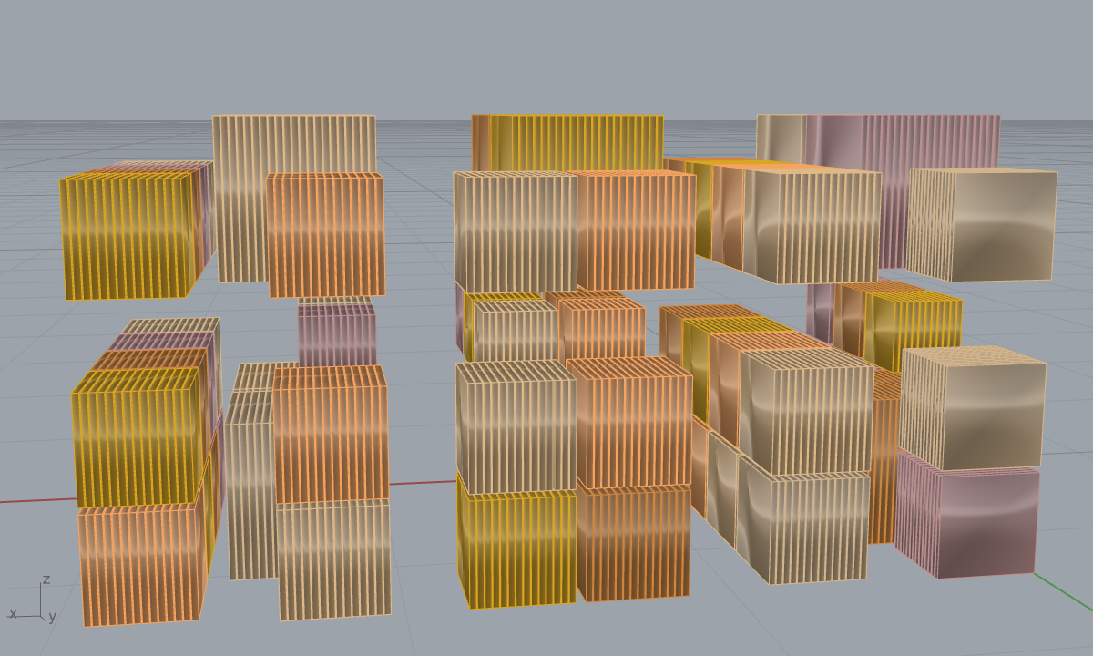
Example 23 runs the full quarry-to-slab chain on a fracture-prone 3.0 x 1.5 x
1.5 m block (6.75 m3): fractures with a 40 mm keep-out leave 6.05 m3 of intact
rock, fracture-aware block packing recovers 2.98 m3 (60 blocks, 49.3% of intact,
100% guillotine-separable), and gangsaw slabbing yields 2.52 m3 of finished 20
mm slab, a 37.3% overall volume yield and 126 m2 of slab face
(examples/23_quarry_to_slab/README.md).
Originality. The slab cutter is clean-room convex-polyhedron half-space clipping (Sutherland-Hodgman family), labelled "Frahan-original" with the optional CGAL boolean backend named separately (
[Algorithm]SlabCutByFracturesComponent.cs:33-39). The successive-plane block-decomposition framing cites Goodman and Shi (1985) block theory (SlabCutter.cs:29-33). The CGAL Polygon Mesh Processing path is GPL and is reached only through the optional shim with a managed fallback (licensing register row 4).
2.6 Example: statue to fabricable blocks¶
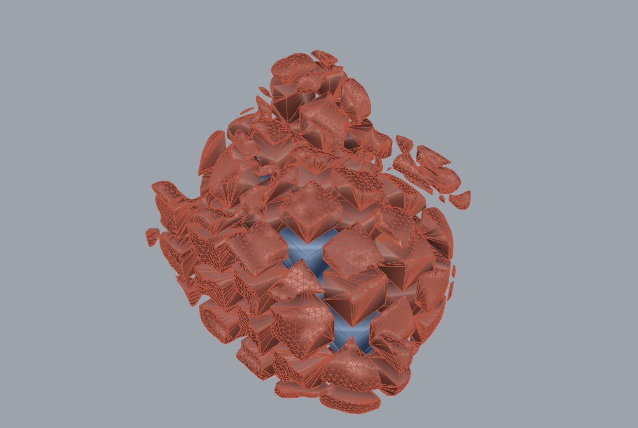
Example 15 is the volumetric counterpart that feeds the packers: it decomposes a
sculpture into roughly 0.5 m brick blocks whose boundary blocks carry the
real statue surface, not bounding boxes. A 0.5 m grid covers the bounding
box; each cell box is intersected (CGAL boolean) with the closed statue solid,
so interior cells return a full cube and boundary cells keep the real mesh face
on the outside and clean planar cut faces on the grid sides. On the Stanford
bunny scaled to 3.0 m, the run produced 7 interior cubes, 106 real-face boundary
blocks, 67 empty cells dropped, 113 closed blocks total, with a recovered volume
ratio of exactly 1.0000 (5.4009 m3 statue = 5.4009 m3 of blocks, measured by
VolumeMassProperties), in 3.6 s over 173 CGAL booleans with zero failures
(examples/15_statue_to_blocks/README.md). The enabling fix is a Geogram
FillHoles -> RemeshUniform -> FillHoles pass that rebuilds the raw scan into a
clean 2-manifold so both the interior point test and the CGAL corefinement work.
These closed blocks are exactly the input the Block Pack (Tree) and DLBF packers
of this chapter consume.
2.7 Status & what's left¶
- Heightmap citation inconsistency.
Pack3DMeshHeightmapComponentlabels the mesh-pile method "Frahan-original" whilePack3DIrregularContainerComponentattributes the identical heightmap method to "Park and Han 2024 tree-packing" ([R8], no DOI, placeholder-grade). The two should be reconciled before external review (Pack3DIrregularContainerComponent.cs:18,Pack3DMeshHeightmapComponent.cs:20-21). Severity: medium (provenance). - Bullet native dependency.
Settle 3Dneedslibbulletc.dllbeside the.gha; without it the component warns and does nothing (BulletSettleService.cs:27,:80-87). It ships ininstall/plugin/but is absent from a source-only build. Severity: medium (deployment). - Settle is non-deterministic. The Bullet solve is a physics simulation, not a deterministic search; example 18 notes one stone hung up mid-drop as a normal settle artifact (11 of 12 clustered). Re-runs can differ. Severity: low (documented behaviour).
- Convex-only managed slab cutter. The default
SlabCutByFracturespath is exact for convex slabs only and "explodes combinatorially on large slabs with many planes"; non-convex or large work needs the opt-in CGAL backend (SlabCutByFracturesComponent.cs:84-92,SlabCutter.cs:23-27). Severity: medium. - Heightmap proxy is a baseline, not the recommended path. The mesh-pile
collision is a conservative vertical-column test on envelopes, not a true 3D
contact solve; the components themselves route users to Settle 3D and Block
Pack (Tree) as the evolved paths
(
Pack3DMeshHeightmapComponent.cs:12-15). Severity: low (by design). - CoACD transitive copyleft. Convex decomposition pulls CoACD, which
vendors CGAL (GPL); the default install must reach it only through the
optional out-of-process shim with the convex-hull fallback
(
docs/thesis/90_originality.md, register row 5). Severity: medium (licensing, mitigated by quarantine).
References (this chapter)¶
- Chehrazad, R., Roose, D., Wauters, T. (2025). A fast and scalable deepest-left-bottom-fill algorithm for the 3D bin packing problem. International Journal of Production Research 63:6606-6629. DOI 10.1080/00207543.2025.2478434.
- Kim, S. (2025). Tree-forest guillotine packing. Computation 13(9):211. DOI 10.3390/computation13090211. (CC BY 4.0.)
- Jalalian, A. et al. (2023). Block-cutting-surface-defined block value (BCSdbBV) cost objective. Scientific Reports. DOI 10.1038/s41598-023-49633-w.
- Park, J., Han, S. (2024). Tree-packing for irregular 3D containers (tree-search 3D-BPP / orthogonal-block packing). (Cited in source; no DOI, placeholder-grade attribution flagged in this chapter.)
- Zhuang, Q., Chen, Z., He, K., Cao, J., Wang, W. (2024). Dynamics simulation-based packing of irregular 3D objects. Computers and Graphics 123:103996. DOI 10.1016/j.cag.2024.103996.
- Wei, J., Liu, M., Wang, J. et al. (2022). Approximate convex decomposition for 3D meshes with collision-aware concavity and tree search (CoACD). ACM Transactions on Graphics (SIGGRAPH 2022) 41(4):42. DOI 10.1145/3528223.3530103.
- Coumans, E. et al. Bullet Physics SDK (rigid-body dynamics, sequential-impulse solver). zlib License. Via BulletSharp.
- Heyman, J. (1966). The stone skeleton. International Journal of Solids and Structures 2(2):249-279. DOI 10.1016/0020-7683(66)90018-7.
- Goodman, R.E., Shi, G. (1985). Block Theory and its Application to Rock Engineering. Prentice-Hall.
- Elkarmoty, M., Bondua, S., Bruno, R. (2020). A combinatorial optimization method for the block-cutting problem. Resources Policy 68:101761. DOI 10.1016/j.resourpol.2020.101761. (Cited by HeteroExt stage 1.)
03. Quarry Block-Cutting Optimization¶
3.0 Scope and lineage¶
This chapter covers the Quarry ribbon tab subset built on the BlockCutOpt
engine: the pose-sweep solver, its recovery and yield objective, the Jalalian
cutting-surface-area-per-value cost axis, the multi-scale recovery cascade, and
the downstream flat-versus-oblique guillotine and gangsaw cost frontier studied
in examples 08, 24, and 25. The core lives at
src/Frahan.StonePack.Core/Masonry/Quarry/BlockCutOpt. The managed solver is a
clean-room reimplementation of the BlockCutOpt brute-force algorithm
(Elkarmoty et al. 2020), whose original implementation is private C++
(BlockCutOpt/README.md:46-50). The repository's tracked delta is documented as
the "14 improvements" table (README.md:185-198), of which 12 of 14 are shipped
(README.md:200). Per the originality framework, the base solver is
clean-room (published math, no upstream source in the tree); the I1 full-3D
pose, the I6/I11 Pareto/BCSdbBV axes, and RecoveryCascade are the
evolved-fork increments claimed in the submitted BoEGE paper
(Murugean 2026, Zenodo DOI 10.5281/zenodo.20608279).
The geological front end (the GPR fracture chain that feeds the tested area) is covered in the GPR chapter; here we take the fracture mesh as given input.
3.1 The block-cut objective: recovery over a pose space¶
3.1.1 Problem statement¶
A quarry bench is an axis-aligned tested region \(\mathcal{A}\subset\mathbb{R}^3\). The rock contains a discontinuity set represented as a triangle soup \(\mathcal{F}=\{T_k\}\) (the fan-triangulated fracture mesh). A cutting grid lays out candidate commercial blocks of fixed size \((L_x,L_y,L_z)\) on a regular lattice. A block is marketable only if it is crossed by no fracture. The decision variables are the rigid pose of the lattice: the yaw \(\psi\) about the vertical axis, the optional tilts \(\theta,\phi\) about the horizontal axes, and the in-plane offsets \((d_x,d_y)\). The objective is to maximise the count of non-intersected blocks.
Let \(G(\psi,\theta,\phi,d_x,d_y)\) be the set of candidate oriented blocks (OBBs) whose footprint lies inside \(\mathcal{A}\). Write the indicator
The non-intersected count is
and the solver returns the argmax over the discretised pose grid:
This is the brute-force search of Elkarmoty et al. (2020), restricted in their
paper to \(\psi\)-only with \(\theta=\phi=0\). The implementation enumerates the
full five-dimensional pose grid (BlockCutOptSolver.cs:108-113).
3.1.2 The cutting-grid pose (I1: full 3D rotation)¶
The original algorithm rotates the lattice only by yaw \(\psi\) about the vertical.
The repository adds tilt about both horizontal axes (improvement I1,
README.md:185). The grid basis is built from the rotation
and the three block axes are \(U=R\,e_x\), \(V=R\,e_y\), \(W=R\,e_z\).
Carrying the product through (the derivation that is inlined and pre-multiplied
in CuttingGrid.cs:91-110) gives, for the in-plane \(U\) axis,
Setting \(\theta=\phi=0\) collapses \(U\to(\cos\psi,\sin\psi,0)\),
\(V\to(-\sin\psi,\cos\psi,0)\), \(W\to(0,0,1)\), recovering the BlockCutOpt-2020
yaw-only grid exactly. This is verified in source: the OrientedBlock
\(\psi\)-only constructor hard-sets \(U_z=V_z=W_x=W_y=0\), \(W_z=1\)
(OrientedBlock.cs:40-50). The lattice centre of cell \((i,j)\) is
with \(c\) the tested-area centroid and \(k\) the saw kerf: the cell pitch is the
block dimension plus the kerf, so the gap between adjacent blocks is exactly the
material lost to the saw (CuttingGrid.cs:77-78, 127-129). A candidate is kept
only if its four horizontal footprint corners lie inside \(\mathcal{A}\)
(CuttingGrid.cs:135-145).
Originality.
CuttingGrid.GenerateTiltedandBlockCutOptSolver: clean-room base (Elkarmoty et al. 2020), with the I1 full-3D pose an evolved-fork increment. Evidence:[Algorithm]atBlockCutOptComponents.cs:97-100("BlockCutOpt brute-force search", Doi 10.1016/j.resourpol.2020.101761; "Full 3D rotation grid", Frahan I1). Tier B for the base, A-candidate-adjacent for the tilt axes.
3.1.3 The intersection predicate (I2/I4)¶
The inner test \(\chi\) is a triangle-versus-OBB overlap. The implementation uses
the 13-axis Separating Axis Theorem of Akenine-Moller (2001): three OBB face
normals \(U,V,W\), the triangle normal, and the nine cross products
\(U,V,W \times e_0,e_1,e_2\) of OBB axis against triangle edge
(ObbTriangleIntersection.cs:10-16). A block is clean iff a separating axis
exists for every nearby triangle. To avoid testing every triangle against every
block, fracture triangles are stored in an axis-aligned BVH and only the leaves
overlapping a block's bound are tested (improvement I2,
TriangleAabbBvh, used at BlockCutOptSolver.cs:243-256). An edge-triangle
variant (Moller-Trumbore) is improvement I4 (README.md:188).
Originality. SAT predicate and BVH: clean-room faithful implementation of published geometry (Akenine-Moller 2001). Evidence:
[Algorithm("Triangle-AABB BVH pruning", "Akenine-Moller 2001 ...")]BlockCutOptComponents.cs:99. Tier C (textbook geometry, engineering value).
3.1.4 Deterministic parallel argmax¶
The pose grid is large; the per-pose grid build and SAT counting are the cost.
The solver enumerates all poses in the exact serial loop order, computes each
pose's count in Parallel.For (every pose reads the immutable BVH and builds its
own grid, so there is no shared mutable state), then takes a serial strict-greater
argmax over the original enumeration order (BlockCutOptSolver.cs:106-135).
Strict-greater (\(>\) not \(\ge\)) means ties resolve to the earliest pose, so the
chosen pose is bit-identical to the serial reference
(SolveInternalSerial, BlockCutOptSolver.cs:151-211), validated headless in
BlockCutOptParallelTests. This is an engineering detail with a real
correctness consequence: parallelism does not perturb the result.
3.1.5 Recovery and yield¶
The reported yield is the kerf-aware recovery of Elkarmoty's thesis Eq. 7-1
(BlockCutOptResult.cs:9-14):
where \(V_B=L_xL_yL_z\) is the block volume and \(V_{\text{kerf}}\) is the volume
lost to the saw inside the grid. The implementation approximates the kerf volume
as a thin film of thickness \(k/2\) over the footprint
(\(V_{\text{kerf}}\approx A_{xy}\,k/2\), BlockCutOptSolver.cs:261-268), and floors
the denominator at \(10^{-12}\) to stay finite. Putting the denominator at the
intact-minus-kerf volume rather than the gross volume means recovery measures
how much of the cuttable rock is captured, not how much of the bench. The
README's documented Stratum-a run returns \(N_{ni}=83\), \(R=44.21\%\), \(\psi=84^\circ\)
on a \(40\times30\times6\) m bench (README.md).
3.2 The Pareto front and the Jalalian I11 cost axis¶
A single recovery scalar hides the economics: more blocks can mean more saw cuts
and a worse cost per unit value. The repository adds a four-objective Pareto
solver (improvement I6, BlockCutOptParetoSolver.cs). Each pose is scored on:
A pose \(p\) dominates \(q\) iff it is no worse on all four axes and strictly better
on at least one; recovery and revenue are maximised, kerf-time and BCSdbBV
minimised (ParetoPoint.Dominates, ParetoPoint.cs:54-71).
3.2.1 BCSdbBV (I11): cutting surface area per block value¶
The fourth axis is the Jalalian et al. (2023) BCSdbBV objective: the total
cut surface area divided by the total recovered block value (improvement I11,
README.md:195, citing Sci. Reports 13, Doi 10.1038/s41598-023-49633-w):
where \(S(b)\) is the OBB surface area
(BlockValueModel.SurfaceArea, BlockValueModel.cs:54-58) and \(\mathrm{BV}_b\) is
the per-block value (default \(=\) block volume, a richer model multiplies by a
class A/B/C price factor, BlockValueModel.cs:22-27). The accumulation runs only
over non-intersected blocks; when no value is recovered the ratio is set to
\(+\infty\) so the pose cannot dominate
(BlockCutOptParetoSolver.cs:82-95). Minimising \(Z_{\mathrm{BCSdbBV}}\) favours
layouts that spend the least saw surface per dollar of stone, which is the
sustainability objective Jalalian formalised to cut quarry waste.
Originality. Pareto solver and BCSdbBV axis: evolved-fork over the single-scalar Elkarmoty objective. Evidence:
[Algorithm]pair atBlockCutOptComponents.cs:306-307("BlockCutOpt omni-solve ... Pareto", Elkarmoty 2020; "BCSdbBV cost objective", Jalalian 2023). The Omni solver composes sub-division, coarse-to-fine search, and the per-zone Pareto front (BlockCutOptOmniSolver.cs:115-178). Tier B (faithful axis from Jalalian, integrated as a new objective).
3.2.2 The cost / volume / balanced frontier (examples 25 and 08)¶
The Pareto front is exercised by a single scalarising knob in the example
studies: the packer maximises \(\mathrm{net} + W\cdot V\), where \(W\) (\(/m^3\)) is a
volume credit swept from cost (\(W=0\)) through balanced to volume
(\(W\to\infty\)). Example 25 (synthetic 6 x 3 x 3 m marble bench, three oblique
fractures, 0.5 m keep-out) reports the measured frontier
(25_cost_metrics.json):
| Objective | \(W\) (\(/m^3\)) | Blocks | Volume | Recovery (intact) | NET |
|---|---|---|---|---|---|
| Max cost | 0 | 15 | 30.5 m3 | 71.8% | $25,650 |
| Balanced | 800 | 20 | 35.5 m3 | 83.5% | $24,650 |
| Max volume | \(10^6\) | 25 | 38.0 m3 | 89.4% | $16,700 |
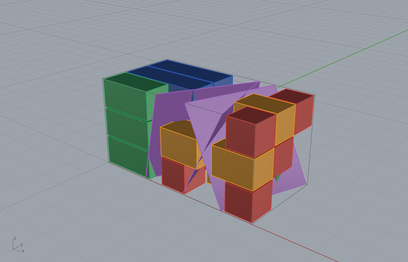
The economics are non-trivial: per the catalogue, price per \(m^3\) falls and cut
cost per \(m^3\) rises as blocks shrink, so the smallest 1x1x1 block has negative
net ($-200) (25_cost_metrics.json catalogue). The trade-off the example
quantifies: cost-to-balanced recovers +5.0 m3 for only -$1,000 net (-3.9%,
marginal \(200/m3), but cost-to-volume costs -\)8,950 (-34.9%) because reaching the
last cells forces premium gangsaw runs to be broken into loss-making offcuts. The
recommended operating point is balanced.
3.3 The bed-bounded hexahedra fix and flat-vs-oblique guillotine (example 08)¶
3.3.1 The bug¶
Example 08 packs real Botticino marble: a 600 MHz GPR grid yields 280 fracture
picks clustered into three dipping beds (0.72 m / 6.1 deg, 2.10 m / 0.9 deg,
3.70 m / 6.1 deg, sub-cm plane-fit RMS) (08_marble_cost_volume_metrics.json).
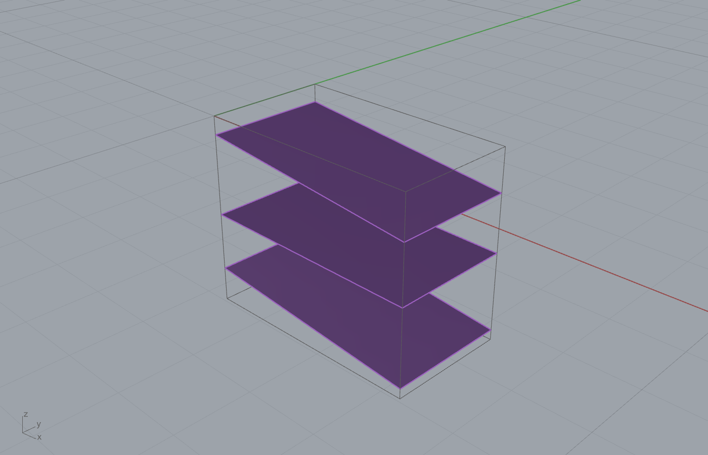
The original layout placed axis-aligned blocks at the mean bed depth. Because
the beds dip ~6 deg, a flat box centred at the mean depth crosses the dipping
bed plane at its ends, so the "intact" block actually straddles a parting. The
fix is to bound each block between the true bed planes rather than at a constant
\(z\): the recovered solids are bed-bounded hexahedra whose top and bottom faces
follow the per-\((x,y)\) bed planes. The metrics note records this directly:
"Block economics use each layer's mean spacing; the oblique geometry follows the
true per-(x,y) bed planes, so displayed blocks never cross a bed"
(08_marble_cost_volume_metrics.json, limitations). Concretely, a block with
footprint \([x_0,x_1]\times[y_0,y_1]\) between an upper bed plane
\(z_u(x,y)=a_u+b_u^x x+b_u^y y\) and a lower bed plane \(z_\ell(x,y)\) has its eight
corners on those two planes, so its local height varies across the footprint and
no corner pierces a parting.
3.3.2 Flat versus oblique guillotine¶
Two cut plans are compared. The flat plan places horizontal full-span cuts at the dip-safe envelope: the top cut at the deepest point of the upper bed, the bottom at the shallowest point of the lower bed, minus the keep-out. The wedges between the flat cut and the dipping bed are waste. This is fabricable on any gangsaw today. The oblique plan tilts each bed-parallel pass to follow the dipping bed, recovering the wedge.
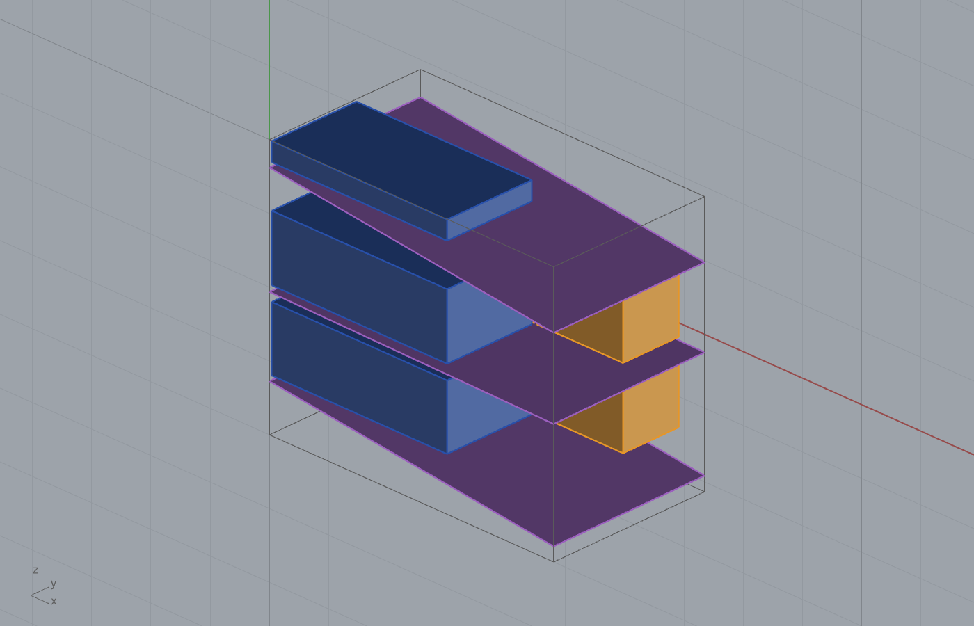
The dip-safe flat layer thicknesses collapse the nominal bed spacing
\([0.72,1.38,1.59,0.30]\) m down to \([0.328,1.051,1.037,0.161]\) m
(flat_guillotine.dip_safe_layers_m), losing the wedge volume. The measured
frontier (oblique vs flat, at max-cost):
| Plan | Volume | NET |
|---|---|---|
| Oblique (bed-following) | 32.16 m3 | $28,741 |
| Flat (orthogonal) | 20.26 m3 | $17,454 |
The georeferencing prize is the gap: oblique recovers +11.90 m3 (+59%) and
+$11,287 net per ~50 m3 bench, entirely because the beds dip ~6 deg. That delta is
the business case for the scanning + georeferenced-marking last mile required to
execute the sloped passes (georeferencing_prize_at_max_cost).
Originality. The bed-bounded hexahedra fix and the flat/oblique frontier are study-level constructions in the example generator, not a Core algorithm class; they are a facade-over-primitives result (bed-plane fitting plus the packing objective composed in the example). The recovery, cost, and frontier numbers are measured, not gated by a Core unit test, so they are REPORTED per the honesty convention. Tier B (engineering study on real data).
3.4 The guillotine cut sequence (example 24)¶
A gangsaw or bridge saw can only make straight edge-to-edge passes. Guillotine
packing guarantees every placed block is reachable by such cuts, so the plan is
directly fabricable. Example 24 renders the literal saw passes that turn a
3.0 x 1.5 x 1.5 m quarry block into 20 dimension blocks of 0.5 m at 10 mm kerf
(grid \(5\times2\times2\)), in the real sequential order
(24_guillotine_metrics.json):
- RIP perpendicular to X \(\to\) 4 rip planes \(\to\) slabs.
- CROSS-Y per slab \(\to\) 5 planes \(\to\) columns.
- CROSS-Z per column \(\to\) 10 planes \(\to\) the 20 finished blocks.
That is 19 guillotine cuts for 20 blocks: each plane spans only its current sub-region, which is the defining property of a guillotine cut.
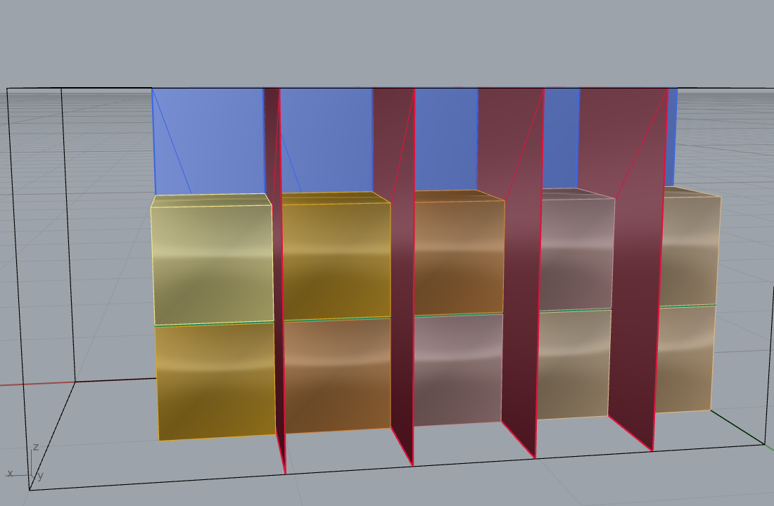
The same hierarchy resolves the balanced packing of example 25 into a saw plan:
two perp-Y cuts (3 slices), two perp-Z cuts (9 beams of 1 x 1 x 6 m), then 25
perp-X rip cuts within each beam, 29 passes total
(25_cost_metrics.json, guillotine_cuts_balanced). The oblique counterpart for
example 08 is 3 tilted bed-parallel passes plus 24 vertical rips, of which only
the 3 tilted passes need georeferenced marking
(oblique_guillotine_cut_plan_balanced).
Originality. Guillotine staging: facade-over-primitives / Tier C. It is standard staged guillotine cutting (Gilmore and Gomory 1965 lineage); the contribution is the rendered, in-order, fabricable saw plan on real geometry, not a new algorithm.
3.5 The recovery cascade (multi-scale reject-recover)¶
RecoveryCascade is the repository's named evolved-fork increment over single-
scale BlockCutOpt. At each scale (coarse \(\to\) fine) the solver runs on the tested
region; non-intersected blocks are recovered, and every block a fracture crosses
is fed back into the same engine at the next finer scale, cutting around the
fracture, until the remnant falls below the smallest marketable size
(RecoveryCascade.cs:9-37). The value recovered from a region \(R\) at scale \(s\)
obeys the recursion (RecoveryCascade.cs:26-29):
where kept/cracked partition the winning grid by the same SAT predicate
!bvh.AnyTriangleIntersects used in the single-scale solver
(RecoveryCascade.cs:91-119). The recursion depth is capped at the number of
scales (RecoveryCascade.cs:74), so it terminates. Crucially, with a single
ScaleSpec the cascade recovers exactly the blocks BlockCutOptSolver.Solve
finds at the same winning pose, so it is a faithful superset that reduces to
BlockCutOpt 2020 (RecoveryCascade.cs:21-24). This reject-coarse / recover-fine
structure is grounded in conditional two-scale cutting (Yarahmadi et al. 2018),
usable-leftover thresholds (Cherri et al. 2009), and staged guillotine cut-up
(Gilmore and Gomory 1965), with the unified 3D recursive form introduced in the
companion paper (RecoveryCascade.cs:31-36).
Originality.
RecoveryCascade: evolved-fork / A-candidate for the unified 3D recursive formulation. Licensing/honesty flag (E9): the header previously self-described "novel"; the audit ruling is to soften this with the BoEGE cite, which the current header does (Murugean 2026, DOI 10.5281/zenodo.20608279). The class is Core-validated (six headless tests per memory) but has no GH consumer; the shippedFractureBlockPackcomponent ships a self-contained recovery engine that calls none ofRecoveryCascade/BlockCutOptSolver/Dlbf3dMixedSizePacker(FractureBlockPackComponent.cs:9-25), a silent-disagreement risk whose resolution is facade-not-fork.
3.6 In-block secondary cutting (AMRR, I9/I12)¶
Improvement I9 couples the quarry-scale solver to in-block secondary cutting via
the Shao et al. (2022) AMRR (Average Material Removal Rate) plane-sequence
strategy (AmrrPlanner.cs:7-31). The planner iteratively cuts a blank convex
polyhedron by planes tangent to a target shape (a bounding sphere in v1): find the
vertex \(P_v\) farthest outside the target, cut by the plane through the tangent
point with normal from centre to \(P_v\), record the step, and repeat until the
outside volume falls below a convergence fraction (AmrrPlanner.cs:132-178). The
objective maximised is the average removal rate
removed volume over cutting time (AmrrPlanResult.Amrr, AmrrPlanner.cs:85),
where the per-cut path length feeding \(\tau_i\) comes from the Minetto et al.
(2017) shared-edge mesh section (improvement I12, SharedEdgeSlicer, used at
AmrrPlanner.cs:171-177). The GH front end is BlockCutOpt AMRR Plan
(GUID F2D0BC03-..., [Algorithm("AMRR in-block plane-sequence cutting",
"Shao, Liu, Gao 2022 ...")], BlockCutOptComponents.cs:215).
Originality.
AmrrPlanner: clean-room faithful implementation of Shao et al. (2022);SharedEdgeSlicerlikewise of Minetto et al. (2017). Tier B.
3.7 Saw-bed scheduling and extraction order (Quarry tab)¶
Two scheduling helpers round out the tab. The Saw Bed Schedule component
assigns recovered blocks to gangsaw beds by greedy LPT (Longest Processing Time)
list scheduling (Graham 1969, [Algorithm("Greedy LPT list scheduling",
"Graham 1969 ...", Doi 10.1137/0117039)],
QuarryCutOptComponents.cs:322). The Extraction Order Optimizer sorts blocks
by a weighted-sum greedy rule with a min-yield skip threshold; its [Algorithm]
attribute honestly records "Frahan-original ... no published scheduling algorithm
matched" (QuarryCutOptComponents.cs:223).
Originality. Saw Bed Schedule: clean-room Graham 1969, Tier C. Extraction Order: original-research / A-candidate (self-declared, prior-art sweep pending). Evidence as cited.
3.8 Heterogeneous facade¶
HeteroExt (Heterogeneous quarry extraction pipeline,
BlockCutOptHeterogeneousComponents.cs:169) is the correct facade pattern: it
composes BlockCutOptSolver plus the Chehrazad et al. (2025) Deepest-Left-Bottom-
Fill 3D mixed-size packer (improvement I7, [Algorithm("Deepest-Left-Bottom-Fill
(3D)", "Chehrazad, Roose, Wauters 2025 ...", Doi 10.1080/00207543.2025.2478434)],
BlockCutOptHeterogeneousComponents.cs:42). Per the HITL ruling its note credits
"interpretation and reimplementation of Elkarmoty 2020 and Chehrazad 2025 ... the
composition and the heterogeneity model are the contribution"
(BlockCutOptHeterogeneousComponents.cs:169).
Originality.
HeteroExt: facade-over-primitives. Tier D for the wrapper; the wrapped DLBF is clean-room Chehrazad 2025 (Tier B).
3.9 Status and what's left¶
- RBE-style correctness is out of scope here but the same audit gates the
quarry tab's honesty conventions. No
BlockCutOptsign-bug is present; the parallel argmax is bit-identical to serial (validated). RecoveryCascadehas no GH consumer (blocker for shipping the cascade on canvas).FractureBlockPackduplicates a recovery engine instead of calling the validated Core cascade; resolution is facade-not-fork.- Coarse-to-fine in the Omni solver is a stub bridge.
UseCoarseToFinecurrently runs the uniform-grid Pareto sweep at the fine step on both branches (BlockCutOptOmniSolver.cs:150-169), the worst-case wall clock; the true coarse-to-fine Pareto sweep is a follow-up. - Kerf volume is a film approximation (\(A_{xy}k/2\),
BlockCutOptSolver.cs:261-268), refined alongside sub-division but not exact. - Two improvements unshipped: I13 (multi-model joint generator, Tian 2025) is
proposed only; I14 (composite multi-convex block, Zhang et al. 2024) is partial
(
README.md:197-200). - Bed-bounded hexahedra and the flat/oblique frontier are example-level, not a Core class; numbers are REPORTED (measured), not gated by a unit test.
- Data licence: example 08 marble GPR data is CC-BY-NC-ND (research/testing
only, not commercial product demos) (
08_marble_cost_volume_metrics.json).
References (this chapter)¶
Akenine-Moller, T. (2001). Fast 3D Triangle-Box Overlap Testing. Journal of Graphics Tools 6(1):29-33.
Cherri, A.C., Arenales, M.N., Yanasse, H.H. (2009). The one-dimensional cutting stock problem with usable leftover. European Journal of Operational Research 196(3):897-908. DOI 10.1016/j.ejor.2008.04.039.
Chehrazad, R., Roose, D., Wauters, T. (2025). A fast and scalable deepest-left-bottom-fill algorithm. International Journal of Production Research 63:6606-6629. DOI 10.1080/00207543.2025.2478434.
Elkarmoty, M., Bondua, S., Bruno, R. (2020). A 3D brute-force algorithm for the optimum cutting pattern of dimension stone quarries. Resources Policy 68:101761. DOI 10.1016/j.resourpol.2020.101761.
Gilmore, P.C., Gomory, R.E. (1965). Multistage cutting stock problems of two and more dimensions. Operations Research 13(1):94-120. DOI 10.1287/opre.13.1.94.
Goodman, R.E., Shi, G.-h. (1985). Block Theory and Its Application to Rock Engineering. Prentice-Hall.
Graham, R.L. (1969). Bounds on multiprocessing timing anomalies. SIAM Journal on Applied Mathematics 17(2):416-429. DOI 10.1137/0117039.
Jalalian, M., Bagherpour, R., Khoshouei, M. (2023). Environmentally sustainable mining in quarries to reduce waste production and loss of resources using the developed optimization algorithm. Scientific Reports 13. DOI 10.1038/s41598-023-49633-w.
Minetto, R., Volpato, N., Stolfi, J., Gregori, R.M.M.H., da Silva, M.V.G. (2017). An optimal algorithm for 3D triangle mesh slicing. Computer-Aided Design 92:1-10. DOI 10.1016/j.cad.2017.07.001.
Murugean, L. (2026). GPR-to-block-yield optimization for fractured dimension-stone quarries (submitted, Bulletin of Engineering Geology and the Environment; reproducibility deposit). DOI 10.5281/zenodo.20608279.
Shao, H., Liu, Q., Gao, Z. (2022). Material Removal Optimization Strategy of 3D Block Cutting Based on Geometric Computation Method. Processes 10(4):695. DOI 10.3390/pr10040695.
Yarahmadi, R., Bagherpour, R., Sousa, L.M.O. (2018). Discontinuity modelling and rock block geometry identification to optimize production in dimension stone quarries. Engineering Geology 232:22-33. DOI 10.1016/j.enggeo.2017.11.006.
Zhang, N., Zheng, H., Yang, M., Wang, N. (2024). An open-source MATLAB toolbox for 3D block cutting and 3D mesh cutting in geotechnical engineering. Advances in Engineering Software 197:103762. DOI 10.1016/j.advengsoft.2024.103762.
03b. Point-Cloud Discontinuity Extraction, Joint Sets, and the DFN¶
3b.0 Scope and lineage¶
Chapter 03 optimises a cutting lattice against a discrete fracture network (DFN) that it takes as given. This chapter builds that network from the upstream evidence: a raw rock-face point cloud. The subsystem turns an unstructured UAV or terrestrial-laser-scan (TLS) cloud into planar facets, clusters their poles into joint sets, reports normal spacing and a Palmstrom block-size estimate, and emits a DFN that feeds the block-cut optimiser of chapter 03. It is the geological front end of the quarry pipeline.
The subsystem is implemented, benchmarked, and live-validated on real clouds. The authoritative sources are the clean-room worker (native/discontinuity_worker/), its README, and the validation report (docs/validation/discontinuity_ingest_card/VALIDATION_REPORT.md). Where a number in this chapter is uncertain or scale-dependent, it says so.
The lineage is conventional structural geology, specifically the joint-set-to-DFN chain codified by Priest (1993) and the ISRM Suggested Methods [R47], implemented as clean-room code. The pole-clustering follows the mean-shift idea of Riquelme et al. (2014, the DSE method); the facet extraction follows the region-grow idea of Dewez et al. (2016, qFacets); the per-point geometry follows Pauly et al. (2002). The stochastic finite-disc DFN rests on the Baecher / Veneziano / Levy-Lee / Priest joint-generator family [R162]. None of these baselines contributes source code. CloudCompare, CCCoreLib, and qFACETS are GPL-licensed and were treated as black-box benchmark baselines only; no GPL source was read or copied. The math is derived from the published papers and from first principles, so the C++ owes nothing to the expression of any GPL tool (native/discontinuity_worker/README.md).
The pipeline has five Grasshopper front ends, all in the Frahan > Quarry tab:
- Discontinuity Sets (Async), GUID D5F10048 (
DiscontinuitySetsAsyncComponent.cs) - runs the worker on a cloud. - Discontinuity Ingest, GUID D5F10049 (
Quarry/DiscontinuityIngestComponent.cs) - reads measured orientations. - Stereonet + Block Size, GUID D5F1004A (
Quarry/StereonetBlockSizeComponent.cs) - projects and reports. - Joint Sets to DFN, GUID D5F1004B (
Quarry/JointSetsToDfnComponent.cs) - deterministic infinite-plane bridge. - Stochastic DFN (Baecher), GUID D5F1004C (
Quarry/StochasticDfnComponent.cs) - finite-disc realisations.
3b.1 The clean-room worker: CSR grid, PCA normals, surface variation¶
The worker is an out-of-process native executable (native/discontinuity_worker/frahan_discontinuity_worker.cpp). It runs outside Rhino so a crash on a malformed 10 M-point cloud cannot take the canvas down with it. It reads a float32 PLY, writes discontinuity.json (the joint sets), facets.csv (the facet poles), and an optional segmented PLY, and returns. The async component D5F10048 launches it and surfaces the results, with a synchronous fallback for headless testing.
The cloud is \(P = \{p_i \in \mathbb{R}^3\}\), \(i = 1..N\). Coordinates are shifted by \(p_i \leftarrow p_i - p_{\min}\) to a local origin, so single-precision float carries about \(10^{-7}\) of the extent, sub-millimetre on a 50 m face. Unit normals are folded to the lower hemisphere, \(n_z \le 0\). Poles are axial, undirected, so \(n \equiv -n\) and the lower-hemisphere representative is canonical.
Per-point normal. For each point the worker gathers a neighbourhood \(N_i\) (the \(k\) nearest points, default \(k = 24\)), forms the centroid \(c\), and accumulates the covariance
With eigenpairs \(\lambda_0 \le \lambda_1 \le \lambda_2\), the normal is the direction of least variance, \(n = v_0\). This is total least squares: the orthogonal-distance best-fit plane is exactly the smallest-eigenvector problem, so PCA is the optimal plane and no separate fit is needed. The eigensolve uses an analytic closed-form 3x3 symmetric solver, not a Jacobi loop.
Surface variation. Pauly et al. (2002) define the planarity proxy
It goes to \(0\) on a perfect plane and to \(1/3\) when the neighbourhood is isotropic. Because the trace identity gives \(\lambda_0 + \lambda_1 + \lambda_2 = \mathrm{trace}(C) = \sum \lVert q - c \rVert^2\), \(\sigma\) is scale-free. It rejects non-planar seeds and orders the region-grow seeds, flattest first.
The neighbour search is the bottleneck, and the lever. For \(k \approx 24\) the covariance is about 150 floating-point operations per point, trivial. The cost is the neighbour gather and its cache behaviour. A first hash-map grid (unordered_map<cell, vector>) scattered each cell across the heap, one cache miss per neighbour, and reached only about 3x OpenMP scaling on 16 cores: memory-bandwidth bound. The shipped worker replaces it with a counting-sort CSR uniform grid after Hoetzlein (2014, fixed-radius nearest-neighbour cell lists from the SPH and molecular-dynamics literature):
- Hash each point to a cell, \(\mathrm{cell}(p) = (\lfloor (x-x_0)/r \rfloor, \lfloor (y-y_0)/r \rfloor, \lfloor (z-z_0)/r \rfloor)\), linearised to one index.
- Counting-sort into CSR: count points per cell, prefix-sum to
cellStart[], scatter point ids tosortedIdx[]. Build is \(O(N)\) with no comparisons. - A cell's points are contiguous in
sortedIdx, so a cell scan is cache-coherent. - A query scans the 27 cells around the home cell; each candidate is a sequential read.
The point array is then reordered into cell order, so neighbouring cells are near in RAM, which is the dominant lever. Normals-step time is U-shaped in cell size: too fine and shells traverse empty cells, too coarse and each cell holds too many candidates to partial-sort. The minimum is near cell \(\approx 1.3\) times the median spacing (native/discontinuity_worker/README.md).
3b.2 Region-grow facets (FACETS)¶
Facets are extracted by planar region growing after the FACETS / qFacets method of Dewez et al. (2016). Seeds are ordered by ascending \(\sigma\), flattest first. The grow is a breadth-first search over the radius-neighbour graph. A candidate \(q\) joins facet \(F\) with current plane \((n_F, c_F)\) when both hold:
- axial normal agreement, \(\lvert n_q \cdot n_F \rvert \ge \cos\theta_{\max}\), with \(\theta_{\max}\) near 10 to 15 degrees;
- plane band, \(\lvert (q - c_F) \cdot n_F \rvert \le d_{\text{band}}\), with \(d_{\text{band}} \approx 2.5\) times the point spacing.
The plane is refit by PCA as the facet grows. The shipped worker maintains a seed-relative incremental covariance, \(\Sigma q\) and \(\Sigma q q^\top\), and recomputes the eigenpair in \(O(1)\) per accretion rather than re-running a full PCA every 64 points. Adversarial verification replicated this incremental covariance against batch PCA to a relative difference near machine epsilon and confirmed it is translation-invariant to a \(10^7\) shift. That \(O(1)\) refit cut the facets stage from about 3.2 s to about 2.85 to 3.0 s on the Tongjiang cloud. Facets below a minimum point count are dropped. Each surviving facet carries its PCA normal, centroid, and point count.
3b.3 Joint-set clustering (Watson axial mean-shift) and the dip / dip-direction convention¶
Facet poles live on the projective plane \(\mathbb{RP}^2\): they are antipodal, \(x \equiv -x\). The DSE method of Riquelme et al. (2014) clusters poles but takes a preset cluster count. The worker avoids that preset by mode-seeking with the antipodal Watson kernel,
which is the natural axial (bipolar) density on the sphere and is invariant to \(x \leftrightarrow -x\) because it depends on \((m \cdot x)^2\). The weighted mean-shift fixed point, with weight \(w_i\) the facet point count, is
Each seed hill-climbs to a mode, stopping below a small angular change. Modes within a merge angle (axial) are one set, and a set's point share is its facet points over the total. The set count is discovered, not preset. The bandwidth is the granularity knob; on Tongjiang, bw 15 degrees gives a stable 4 sets, bw 10 gives about 10, bw 8 gives about 19. Set count is bandwidth, seeding, and noise sensitive, which is inherent to joint-set identification, not a defect of this implementation.
Determinism was established by adversarial review. A non-stable sort on the seed-order key was replaced by a total order, and the mean-shift now seeds from a hybrid set: strided facet poles plus a fixed Fibonacci hemisphere grid, both order-independent. Two runs are now byte-identical. The Fibonacci grid added one mode the strided-only sample had missed, moving the shipped Tongjiang result from 4 to 5 candidate sets at the comprehensive seeding; the dominant 2 to 3 sets are robust and the marginal sets remain count-sensitive.
Orientation convention. With the geology frame \(x = \text{East}\), \(y = \text{North}\), \(z = \text{Up}\), and \(n\) folded to \(n_z \le 0\) (Discontinuity/OrientationMath.cs):
- dip, \(\delta = \arccos(\lvert n_z \rvert) \in [0\degree, 90\degree]\);
- dip direction, \(\alpha = \mathrm{atan2}(n_x, n_y) \bmod 360\degree\), clockwise from North;
- strike \(= (\alpha - 90\degree) \bmod 360\degree\), pole trend \(= (\alpha + 180\degree) \bmod 360\degree\), plunge \(= 90\degree - \delta\).
The forward map reads the down normal; its inverse computes \(n = (\sin\delta \sin\alpha,\ \sin\delta \cos\alpha,\ -\cos\delta)\), flipping only the \(z\) sign, the correction recorded when the ingest path was first wired (see the validation report).
3b.4 ISRM distinct-joint spacing (the original fix)¶
Spacing is the geotechnically load-bearing number, and it carried two distinct errors that were corrected. Both fixes are original to this work.
Fix 1: the home-cell neighbour bug. The first hash-map kNN advanced its search ring before scanning, so it skipped the query's home cell and measured the nearest neighbour in an adjacent coarse cell. That over-estimated point spacing roughly tenfold, about 0.078 m against a true 0.008 m on Tongjiang. The inflated spacing inflated the region-grow plane band (\(2.5 \times \text{spacing}\)), which over-merged the joint sets, so only 2 sets were found. The CSR kNN starts at ring 0, recovers the correct 0.008 m spacing, tightens the band, and resolves 4 well-separated sets. The evolved worker is therefore both faster and more geologically correct.
Fix 2: facet-gap spacing versus distinct-joint spacing. Within a set, the facet centroids project onto the set normal as scalar offsets \(s_k = c_k \cdot n_{\text{set}}\). The first method sorted these offsets and reported the mean consecutive gap as the spacing. That measured the sampling density of facets along the normal, not the distance between physical joints, and it returned spacings far too small to be a real fracture spacing. The fix clusters the sorted offsets into distinct joints with a gap threshold (the gap exceeds the larger of several times the median gap and twice the point spacing), then reports the cluster-to-cluster distances as the spacing and the cluster count as the number of joints. This is the ISRM-faithful "spacing along a scanline" of Priest (1993, chapter 4) and the ISRM Suggested Methods [R47]: spacing is the true perpendicular plane-to-plane distance.
The before-and-after is visible in the numbers. The honest, ISRM-fixed Tongjiang spacings are decimetre-scale per set: 0.2478, 0.2344, 0.6735, 1.1084 m. The honest realisation on a small blank yields distinct fracture planes at a dominant spacing of about 0.19 to 0.38 m with no scale fudge factor, where the earlier averaged-facet-gap method had returned spacings one to two orders of magnitude smaller.
3b.5 Stereonet and Palmstrom block size¶
The Stereonet + Block Size component D5F1004A consumes the per-set dip, dip direction, spacing, and share, plus the facet poles, and draws itself on the canvas in DrawViewportWires. It is self-presenting: reopening the saved definition cold reproduces the net, great circles, set poles, facet-pole density, and the block-size readout, with no external bake script.
Projection. The default is the equal-area (Schmidt / Lambert) lower-hemisphere net (Discontinuity/StereonetProjection.cs). For a pole at colatitude \(\theta = \arccos\lvert n_z \rvert\) and azimuth \(\varphi = \mathrm{atan2}(n_x, n_y)\),
A Wulff (equal-angle) toggle swaps to \(r = \tan(\theta/2)\). The mapping is monotone: dip 0 maps to the centre, dip 90 maps to the rim.
Block size (Palmstrom 2005). Inter-set axial angles are \(\gamma_{jk} = \arccos\lvert n_j \cdot n_k \rvert\). With three dominant sets of spacings \(s_1, s_2, s_3\) (Discontinuity/BlockSizeMath.cs):
- volumetric joint count \(J_v = \sum_j 1/s_j\), with single-plane sets (\(s_j \le \varepsilon\)) skipped to guard the division;
- block volume \(V_b = \dfrac{s_1 s_2 s_3}{\sin\gamma_{12}\,\sin\gamma_{23}\,\sin\gamma_{31}}\), reducing to \(s_1 s_2 s_3\) for orthogonal sets;
- block-size index \(I_b = (s_1 + s_2 + s_3)/3\), equivalent diameter \(D_{eq} = V_b^{1/3}\);
- RQD proxy \(\mathrm{RQD} \approx 110 - 2.5\,J_v\), clamped to \([0, 100]\).
When fewer than 3 sets are present the blocks are unbounded slabs or columns, and the component emits a descriptor rather than a \(V_b\). A synthetic check with 3 orthogonal sets at spacings 1.0, 1.5, 2.0 m returns \(V_b = 3.000\,\text{m}^3\), \(J_v = 2.1667/\text{m}\), \(D_{eq} = 1.442\), matching the closed form.
Units are the highest risk. A detail scan reports spacings in metres on a centimetre-scale object. On the raw Tongjiang detail scan (\(s\) of 0.003 to 0.012 m) a naive read gives \(J_v\) of hundreds per cubic metre and \(\mathrm{RQD} = 0\), physically meaningless at that scale. The component therefore displays spacing units, accepts a unit scale, and shows a PROXY label when the user maps the cm-scale detail scan to a metre-scale bench (docs/validation/discontinuity_ingest_card/VALIDATION_REPORT.md). With the ISRM distinct-joint fix the metre-scale spacings are honest without any scale fudge, and the unit guard is then a safety net, not a correction.
3b.6 Measured-orientation ingest (CSV / GeoJSON / DXF / SHP)¶
Not every input is a cloud. A field survey or a CloudCompare / Compass session exports orientations directly, so the Discontinuity Ingest component D5F10049 reads measured discontinuities from four formats (Discontinuity/Ingest/DiscontinuityReader.cs, Discontinuity/Ingest/Discontinuity.cs). The reader dispatches on extension:
- CSV (hand-rolled, dependency-free): sniffs the delimiter and a case-insensitive header, and accepts
dip,dipdir[,x,y,z], normal columnsnx,ny,nz[,x,y,z], or plane coefficients \(a,b,c,d\) with \(n \cdot p = d\) giving centroid \((d/\lvert n \rvert^2)\,n\). - GeoJSON (NetTopologySuite.IO.GeoJSON): point features with
dip/dipdirproperties become planes; LineString and MultiLineString become traces; thecrsis read when present. - DXF (hand-rolled ASCII group-code reader):
LINE,LWPOLYLINE,POLYLINE/VERTEX, and3DFACEentities; polylines become traces, 3DFACE becomes a plane. - Shapefile (NetTopologySuite.IO.Esri): points and lines as for GeoJSON, carrying the sidecar
.prjWKT into the collection's CRS field.
A trace is fit to a plane by PCA total least squares, the same smallest-eigenvector idea as the worker. The model is a Discontinuity (normal, centroid, optional trace polyline, kind, set id, cached dip / dip-direction, source) gathered into a DiscontinuityCollection. Bad rows are skipped with a warning, never thrown, per the project "log, skip, continue" policy. The component outputs oriented planes, traces, dip, dip direction, set id, and a report.
Live validation fed the discovered Tongjiang sets back through D5F10049 as dip,dipdir,set,x,y,z. It parsed the features to oriented planes with 0 warnings, and the dip / dip-direction round-tripped exactly: the shallow set baked near-flat and the steep sets baked steep, geometrically correct (docs/validation/discontinuity_ingest_card/VALIDATION_REPORT.md).
3b.7 The Joint-Sets-to-DFN bridge (infinite-plane, deterministic)¶
The simplest DFN treats each joint as an infinite plane spanning the bench, which is the right model when joints are persistent relative to the block size. The Joint Sets to DFN component D5F1004B wraps JointSetDfnGenerator.Generate, which builds fracture planes from joint sets and a bounding box. The algorithm is the scanline construction of Priest (1993, chapter 4) [R47]:
- Project the 8 bounding-box corners onto a set's normal, giving a range \([t_{\min}, t_{\max}]\) relative to the box centre.
- Walk the range in steps of the mean spacing, starting from a uniformly random offset in \([0, \text{spacing})\).
- Emit a plane at \((\text{boxCentre} + t\,n)\) for each step.
Spacing is constant by default, or negative-exponential when requested, with the step \(-\ln(1-U)\cdot\text{spacing}\) for \(U \sim \text{Uniform}(0,1)\). The orientation can carry a small Gaussian scatter about the mean, built from two in-plane Box-Muller samples, a small-angle Fisher approximation. The whole construction is deterministic given the seed, and a hard per-set plane limit guards against a spacing too small for the box. The JointSet orientation convention matches section 3b.3: dip direction clockwise from North, dip from horizontal, normal computed from the pair. The emitted planes feed the slab cutter and from there the block-cut optimiser of chapter 03. Source: Masonry/Quarry/JointSetDfnGenerator.cs, Masonry/Quarry/JointSet.cs.
3b.8 The Baecher stochastic finite-disc DFN and Monte-Carlo block yield¶
Persistent infinite planes overstate connectivity. A real joint terminates, and a finite disc is the standard stochastic model. The Stochastic DFN (Baecher) component D5F1004C wraps BaecherDfnGenerator (Masonry/Quarry/BlockCutOpt/BaecherDfnGenerator.cs), a clean-room implementation of the Baecher et al. (1977) finite-disc model from the joint-generator family [R162]. Each realisation draws disc centres as a Poisson point process, pole orientations from a Fisher (1953) distribution about the set mean with dispersion \(\kappa\), and disc radii from a lognormal distribution. The disc count for a set follows the intensity relation
where \(P_{10}\) is the linear fracture frequency along the set normal, \(V\) the bench volume, and \(\mathbb{E}[r^2]\) the second moment of the radius law. The Fisher dispersion is fit from the per-set pole scatter; the radius law is fit from the in-plane facet traces.
Block yield is a distribution, not a point estimate. Because the DFN is stochastic, the optimiser of chapter 03 is run over \(M\) independent realisations and the marketable-block count is reported as a distribution. The wrapper runs \(M\) seeds, draws one DFN realisation per seed, solves block-cut on each, and reports the \(p_{10}\), \(p_{50}\), \(p_{90}\), mean, and standard deviation of recovery plus the most-common best direction. The \(p_{10}\) recovery is the robust score: the yield that survives fracture-mapping uncertainty. On a synthetic 4 x 4 x 4 m bench, \(M = 20\) realisations with a mean of about 237 fractures yield, for a 0.5 m target block, a mean of 7.3 blocks (standard deviation about 2.7, range 4 to 13); for a 0.8 m target, a mean of about 0.6 (range 0 to 2); for a 1.2 m target, 0 blocks in all 20 realisations. The spread across seeds is the point: a single deterministic solve would have reported one number and hidden the variance.
Benchmark and the corrected framing¶
The shared bottleneck of every discontinuity pipeline is per-point normal estimation, so that is the benchmarked operation. The cloud is the Tongjiang quarry-face detail_cloudXB.ply at 7,858,334 points, on a 16-logical-core machine with a static mingw64 build. An apples-to-apples comparison requires the same neighbourhood definition, so kNN and radius are reported separately.
At a matched \(k = 24\) neighbourhood, the shipped double-precision worker computes the normals in about 10.2 s against Open3D 0.19's KD-tree at 14.78 s, about 1.4x faster. A single-precision structure-of-arrays bench variant reaches about 8.0 s, about 1.85x. The speedup comes from the counting-sort CSR build (about 0.7 s, \(O(N)\)), the cache-coherent point reorder, the analytic eigensolver, and the float coordinate layout.
The earlier "215x / 265x faster than CloudCompare" claim is retracted. CloudCompare's octree took about 2127 s, but it ran at radius 0.5 m, which spans thousands of neighbours per point on this 8 mm-spacing cloud, a far larger neighbourhood than \(k = 24\). That is a scale reference, not a like-for-like speedup. The defensible win is the about 1.4x over Open3D at matched \(k = 24\), plus a Rhino-free, single-executable, deterministic worker. The whole discontinuity pipeline, normals plus facets plus Watson sets, runs end-to-end in about 13.6 to 14.7 s, with normals the dominant stage (native/discontinuity_worker/README.md).
Live validation, and a validity gate¶
The first acceptance rule is geological, not numerical: confirm the scan is a clean in-situ exposure before trusting the joint sets. A muck pile, a vegetated slope, or a registration crop will produce confident but meaningless sets, because the surfaces are loose-block faces, not joints (docs/rockfaces_dataset.md). The validity gate checks the assigned point share and an edge-on view.
Granite Dells, Arizona (valid in-situ case). A clean TLS granite outcrop, OpenTopography OT.122010.26912.1, 4,977,725 points at about 0.0141 m spacing. The worker found 3 sets in about 9.1 s: a near-horizontal sheeting joint at dip 3.13 degrees and two near-vertical sets at dip 88.66 and 89.19 degrees, with spacings 0.2814, 0.3361, 0.3954 m and point shares 0.63, 0.19, 0.18. The sheeting joint plus two orthogonal vertical sets is the textbook granite block structure (docs/validation/discontinuity_ingest_card/CLEAN_GRANITE_DELLS.md).
Finestrat, Alicante (valid complete-face case). A gypsum rock slope, the Riquelme / DSE reference dataset (Zenodo 7576524, CC-BY-4.0), 1,738,184 points, downsampled to 869,092. The worker found 3 sets in about 1.36 s at dips 85.1, 37.8, 86.8 degrees and spacings 1.68, 1.95, 1.83 m. This is the cleanest complete-face demonstration, because the scan is a full exposed slope rather than a detail crop (docs/rockfaces_dataset.md).
Tongjiang, Sichuan (cautionary case). The detail-scan cloud at 7,858,334 points runs the full pipeline in about 14.6 s and yields 4 sets at dips 19.3, 78.75, 72.27, 83.47 degrees and ISRM-fixed spacings 0.2478, 0.2344, 0.6735, 1.1084 m. The comprehensive Fibonacci seeding surfaces a 5th marginal set. The card run at unit scale 100, the cm-detail-to-bench proxy, reported \(J_v = 7.20\), \(\mathrm{RQD} = 92\), \(V_b = 0.352\,\text{m}^3\), \(D_{eq} = 0.71\) m and is labelled PROXY in the component. The cautionary flag stands: the originals are a loose-rock muck-pile scan, not an in-situ exposure, so Tongjiang exercises the software end to end but is not a valid dimension-stone deposit (docs/validation/discontinuity_ingest_card/VALIDATION_REPORT.md, docs/rockfaces_dataset.md).
Both new components built clean against net48, and all three (D5F10048, D5F10049, D5F1004A) register in a fresh Rhino 8 with the deployed .gha. The Core uses Rhino.Geometry types whose native operations call rhcommon_c.dll, which only initialises inside a live Rhino. The reader tests therefore SKIP cleanly headless and are covered live; the block-size, orientation, and stereonet math tests run headless and PASS, for 0 failures (docs/validation/discontinuity_ingest_card/VALIDATION_REPORT.md).
3b.9 Status and what is left¶
Established and live-validated:
- Clean-room CSR worker: \(k = 24\) PCA normals on the 7.86 M-point Tongjiang cloud in about 10.2 s, about 1.4x faster than Open3D's KD-tree at matched \(k = 24\); full pipeline about 14.7 s, deterministic.
- FACETS region-grow with \(O(1)\) incremental covariance, and Watson axial mean-shift joint-set clustering with a discovered set count.
- ISRM distinct-joint spacing, the two-part original fix, giving honest decimetre spacings.
- Stereonet plus Palmstrom block size, self-presenting on canvas, units-guarded.
- Four-format measured-orientation ingest (CSV, GeoJSON, DXF, SHP).
- The deterministic infinite-plane DFN bridge to chapter 03, and the Baecher finite-disc DFN with Monte-Carlo block yield.
- Three valid in-situ validations: Granite Dells (3 sets), Finestrat (3 sets), plus Tongjiang as the worker exercise and muck-pile cautionary case.
Honest limitations:
- Persistence is censored. A surface scan sees the trace, not the buried extent of a joint, so the persistent fraction and the radius law are partly extrapolated. The DFN disc sizes inherit that censoring.
- The lognormal radius coefficient of variation is assumed, not measured from independent data; it is fit from in-plane facet traces, which are themselves censored.
- Yield is a distribution, not a point estimate. The Monte-Carlo wrapper reports \(p_{10}\) / \(p_{50}\) / \(p_{90}\) over seeds for exactly this reason; a single deterministic solve would hide the variance.
- Set count is bandwidth, seeding, and noise sensitive. The dominant 2 to 3 sets are robust; the marginal sets and the exact count are inherently sensitive.
- The validity gate is advisory, not automatic. The user must confirm a clean in-situ exposure; the software cannot yet reject a muck-pile scan on its own.
Next:
- A point-share floor and a stability-based bandwidth pick, to make the set count robust across clouds without manual bandwidth tuning.
- A matched radius-0.5 control (worker and Open3D both at radius 0.5) to fully decompose the algorithm gain from the neighbourhood gain.
- Per-physical-plane density clustering as the v2 refinement of the distinct-joint spacing, replacing the sorted-offset gap clustering.
References (this chapter)¶
The two project-global references reused here:
- [R47] ISRM Suggested Methods (1978) and Priest, S. D. (1993), Discontinuity Analysis for Rock Engineering - joint-set definition, scanline spacing, and the infinite-plane DFN basis.
- [R162] Tian (2025) and the Baecher / Veneziano / Levy-Lee / Priest joint-generator family - stochastic finite-disc DFN models.
New sources cited in this chapter (listed here, not assigned global R-numbers):
- Baecher, G. B., Lanney, N. A., and Einstein, H. H. (1977). Statistical description of rock properties and sampling. 18th U.S. Symposium on Rock Mechanics. Finite-disc DFN model: Poisson centres, Fisher poles, lognormal radii.
- Dewez, T. J. B., Girardeau-Montaut, D., Allanic, C., and Rohmer, J. (2016). FACETS: a CloudCompare plugin to extract geological planes from unstructured 3D point clouds. ISPRS Archives XLI-B5. Planar region-growing facet extraction (qFacets); used as a black-box baseline, not as source.
- Fisher, R. A. (1953). Dispersion on a sphere. Proceedings of the Royal Society A 217(1130):295-305. Orientation scatter via the dispersion parameter \(\kappa\).
- Hoetzlein, R. (2014). Fast fixed-radius nearest neighbors: interactive million-particle fluids. GPU Technology Conference. Counting-sort uniform-grid cell lists.
- Palmstrom, A. (2005). Measurements of and correlations between block size and rock quality designation (RQD). Tunnelling and Underground Space Technology 20(4):362-377. Block volume, \(J_v\), and RQD relations.
- Pauly, M., Gross, M., and Kobbelt, L. P. (2002). Efficient simplification of point-sampled surfaces. IEEE Visualization 2002. Surface variation \(\sigma = \lambda_0 / (\lambda_0 + \lambda_1 + \lambda_2)\).
- Riquelme, A. J., Abellan, A., Tomas, R., and Jaboyedoff, M. (2014). A new approach for semi-automatic rock mass joints recognition from 3D point clouds. Computers and Geosciences 68:38-52. The DSE method; mean-shift pole clustering, used as a black-box baseline.
04. GPR Fracture & Cavity Mapping¶
This chapter covers the geophysical front end of the repository: the
ground-penetrating-radar (GPR) processing chain that turns a raw B-scan into a
fracture map, the surface fitting and uncertainty ladder that turn that map into
a quantified keep-out volume, and the earthworks reducers that lift a bedrock
surface out of the same picks. The subsystem lives under Quarry/Processing,
Quarry/Ingestion, and Earthworks in the Core assembly, with seven Grasshopper
adapters on the Frahan > Quarry ribbon. It is the geological front end that
chapter 3 (Quarry Block-Cutting) forward-references: chapter 3 takes the fracture
mesh as given input, and this chapter builds it
(docs/thesis/chapters/03_quarry-blockcut.md:21-22).
The whole pipeline is pure managed code. There is no MathNet, no Python runtime,
no native shim on the processing path; the FFT, the Hilbert transform, the
kriging, and the error function are all in-tree. This is a deliberate
constraint: the prototype that the C# Core mirrors was a Python/numpy/scikit-learn
script, and the port to dependency-light managed code is what makes the chain
installable beside the .gha without forcing scipy onto every machine
(RadargramProcessor.cs:9-30, Kriging.cs:8-29). The derivations below reuse
the mathematics validated in the submitted BoEGE paper (Murugean 2026), which
this subsystem underlies.
The core physical model is the constant-velocity time-to-depth conversion. A GPR records two-way travel time \(t\); with electromagnetic velocity \(v\) in the rock, the reflector depth is
where \(c=0.299792458\,\mathrm{m/ns}\) and \(\varepsilon_r\) is the relative
permittivity (marble \(\varepsilon_r\approx9\), \(v\approx0.10\,\mathrm{m/ns}\);
granite \(\varepsilon_r\approx6\), \(v\approx0.12\,\mathrm{m/ns}\)). Velocity is the
single highest-leverage value in the whole chain because every depth scales with
it linearly (RadargramProcessor.cs:27-28; GprPresets.cs:18-19). The
[Algorithm] attribute on the front-end component states the model in one line:
"v=c/sqrt(eps_r); depth=v*t/2. Energy E=|s+iH{s}|^2; fractures are high-E
continuous reflectors, intact stone is low-E"
(GprFractureExtractComponent.cs:43-45).
4.1 Ingestion and the file dispatcher¶
The single canvas-side entry point is GprFileReader.Load, which dispatches by
extension to the format reader: CSV, SEG-Y (.sgy/.segy), MALA (.rd3),
Sensors & Software pulseEKKO (.dt1), IDS GeoRadar (.dt), and GSSI (.dzt)
(GprFileReader.cs:23-46). The proprietary Geoscanners AKULA .gsf format is
explicitly not guessed: the reader raises a NotSupportedException that tells
the user to convert to SEG-Y with GPRSoft or RGPR first, because the binary spec
is closed (GprFileReader.cs:46-51). This is the bridge-not-guess posture: a
wrong header guess on a proprietary container would silently corrupt the depth
axis.
RadargramProcessor.ToGrid builds the regular [samples, traces] amplitude grid
and recovers the true two-way sample interval \(\mathrm{d}t\) in nanoseconds,
velocity-independent, so the caller scales depth with the stone velocity rather
than baking a velocity into ingest. It prefers the reader-supplied
SampleIntervalNs; only when that is unknown does it fall back to recovering
\(\mathrm{d}t\) from the metres-per-sample step at vacuum velocity
(\(\mathrm{d}z=c\,\mathrm{d}t/2\)) (RadargramProcessor.cs:42-75).
Originality.
GprFileReaderand the per-format readers are vendored-library / clean-room depending on the format: each reader implements a published or open binary spec (pulseEKKO DT1/HD is the public-domain USGS OFR 02-166 spec, Lucius and Powers 1999; SEG-Y is the SEG standard). The dispatcher itself is a thin switch and adds no algorithm. No proprietary spec is reverse-engineered.
4.2 The B-scan processing chain¶
RadargramProcessor.Run is the validated chain, mirroring the Python prototype
stage for stage (RadargramProcessor.cs:334-357):
The early stages are elementary 1-D filters: dewow is a high-pass running-mean
subtraction that removes the low-frequency "wow" baseline drift
(Dewow, :100-115); background removal subtracts the mean trace to kill
horizontal banding and the direct air-wave (:152-163); the time-zero mute
zeroes the air-wave / antenna-coupling band (:165-170); t-power gain
multiplies by \((i\,\mathrm{d}t+1)^p\) to compensate spherical divergence and
absorption (:172-182). Each box-mean uses an \(O(\mathrm{len})\) running sum with
numpy 'same' edge semantics so the C# output is bit-comparable to the
prototype (BoxMeanSame, :83-98). The column operations are independent, so
they run as deterministic Parallel.For with thread-local scratch (a fixed
output partition makes the parallel result bit-identical to the serial loop,
:104-114, :295-307).
Originality. The dewow / background / mute / gain / AGC primitives are clean-room standard GPR processing (Annan 2009; Neal 2004), implemented from published signal-processing definitions with no upstream code in the tree. The contribution is the validated ordering and parameterisation, not the filters.
4.2.1 The FFT and Hilbert transform (clean-room numerics)¶
The spectral stages need an exact-length forward and inverse transform that
matches numpy.fft. The in-tree Fft is a radix-2 Cooley-Tukey transform
(Cooley and Tukey 1965) for power-of-two lengths, with a Bluestein chirp-z
fallback for arbitrary lengths so the 2-D Stolt migration and the Hilbert
envelope operate on the exact sample and trace counts; zero-padding would
shift the frequency grid and bias the migration (Fft.cs:30-94). The Bluestein
plan (the chirp and the precomputed kernel spectrum) is length-only, so it is
built once per distinct length and reused across every trace, the single biggest
speed-up for the 986-same-length envelope loop (Fft.cs:96-149).
The instantaneous-energy attribute is the analytic-signal magnitude. For a real trace \(s\), the analytic signal is \(s+i\,\mathcal{H}\{s\}\), where \(\mathcal{H}\) is the Hilbert transform; the instantaneous amplitude (envelope) is its magnitude and the instantaneous energy is the square:
The envelope is computed by the spectral method (Taner, Koehler and Sheriff
1979): forward-FFT the trace, apply the one-sided weighting
\(H=[1,2,2,\dots,2,1,0,\dots,0]\) that doubles the positive frequencies and zeroes
the negatives, inverse-FFT, take the magnitude (AnalyticEnvelope,
Fft.cs:159-185; HilbertEnergy, RadargramProcessor.cs:293-308). The physical
reading is the literature consensus: a fracture or cavity is an impedance
contrast that reflects strongly, while intact stone is the low-energy background
(Porsani et al. 2006; Isakova 2021), so high instantaneous energy is the fracture
proxy.
Originality.
Fftis clean-room: a numerical method (radix-2 + Bluestein) is not copyrightable and the file says so (Fft.cs:16-18). The Hilbert-envelope attribute is the textbook Taner et al. (1979) complex-trace analysis, cited in the front-end[Algorithm](GprFractureExtractComponent.cs:44).
4.2.2 Stolt f-k migration with half-velocity (original derivation)¶
Diffraction hyperbolae and dipping reflectors are mispositioned in the raw B-scan; migration collapses diffractions and moves dipping events to true position. The repository implements Stolt (1978) f-k migration in the exploding-reflector model. The key step is the constant-velocity dispersion relation that maps the recorded temporal frequency \(\omega\) to the vertical wavenumber \(k_z\).
Derivation. A monochromatic plane wave in the exploding-reflector model travels at the migration velocity \(v_m=v/2\) (the half-velocity that converts two-way time to one-way depth). Its dispersion relation links the temporal frequency \(\omega\) to the spatial wavenumbers \((k_x,k_z)\):
Solving for the source frequency at a target output wavenumber \(k_z=\omega/v_m\) gives the Stolt remap: each output cell \((k_z,k_x)\) samples the recorded spectrum at
and because the remap stretches the frequency axis non-uniformly, energy must be rescaled by the Stolt Jacobian \(\partial\omega'/\partial k_z\):
The implementation builds the 2-D spectrum on the exact grid, applies the
remap by linear interpolation in \(\omega\), multiplies by \(J\), and inverse-FFTs
(StoltMigration, RadargramProcessor.cs:199-291; remap and Jacobian at
:259-267). The half-velocity \(v_m=v/2\) is set explicitly at :208, the depth
floor that the rest of the chain depends on.
The repository adds a cosine dip-taper that the bare Stolt operator lacks. Steep-dip events near the evanescent boundary \(|v_m k_x|/|\omega|\to1\) alias; the taper smoothly zeroes the spectrum there:
which suppresses steep-dip aliasing before the remap (:235-244). The
frequency grids \(\omega\) and \(k_x\) follow the numpy.fftfreq ordering exactly
(FftFreq, :361-370) so the migrated section matches the validated prototype.
Originality. Stolt migration is clean-room from Stolt (1978), cited in the
[Algorithm]attribute (GprFractureExtractComponent.cs:44). The half-velocity exploding-reflector model and the Jacobian are the published method. The cosine dip-taper is a small evolved anti-alias addition on top of the bare operator; it is an engineering delta, not a new migration.
4.2.3 Depth equalisation¶
A locally strong deep reflector still reads weaker than a shallow one because
absolute energy decays with depth. DepthEqualizeEnergy normalises each depth row
by a smoothed per-row median, so a deep fracture surfaces at the same relative
energy as a shallow one (:310-332). This is the relative-amplitude display
behind the energy section; it is a display normalisation, not a detector, and it
is preset-toggleable.
4.3 Fracture extraction: high energy plus dip-aware continuity¶
FractureExtractor.Extract consumes the instantaneous-energy section and applies
two rules from the reviewed literature (FractureExtractor.cs:8-24).
Rule 1, high-energy local maxima. A sample is a candidate if its normalised
energy exceeds a high quantile (default \(0.985\)) and it is a per-column local
maximum (:64-74). The quantile is a robust threshold: the top 1.5% of energy is
the reflector population, the rest is intact-stone background.
Rule 2, the USGS lateral-continuity criterion. A genuine reflector is
laterally continuous; an isolated bright spot is clutter or a point
diffraction. The USGS Mirror Lake protocol keeps a pick only if at least a
minimum number of like picks fall within a horizontal window (the granite default
is \(\ge40\) traces \(\approx1\,\mathrm{m}\)) in a narrow depth band
(:18-21, :30-35). The repository evolves the flat-horizon version of this
test into a dip-aware filter.
Original derivation: dip-aware continuity. A horizontal running-sum counts
support only along sub-horizontal reflectors and rejects dipping shear zones that
are real. To follow a dip, the extractor shears the mask so a reflector of slope
\(\sigma\) (samples per trace) becomes horizontal, counts support along the now-flat
event over the trace window, unshears, and keeps the maximum support over a
set of candidate slopes (:76-130). The slope range is bounded by the maximum
dip the filter follows. Mapping a dip angle \(\theta\) to a sample slope uses the
depth-per-sample \(\Delta=v\,\mathrm{d}t/2\) and the trace spacing \(\mathrm{d}x\):
with \(\theta_{\max}=45^\circ\) by default; events steeper than the gate find no
matching slope and are rejected, enforcing the USGS \(<45^\circ\) continuity gate
(:80-91, DipMaxDeg :36-40). The kept picks carry depth \(v(i\,\mathrm{d}t)/2\)
and a normalised-energy confidence (:132-143), then convert to
world-coordinate GprReflectorPick records using the trace positions
(:146-159).
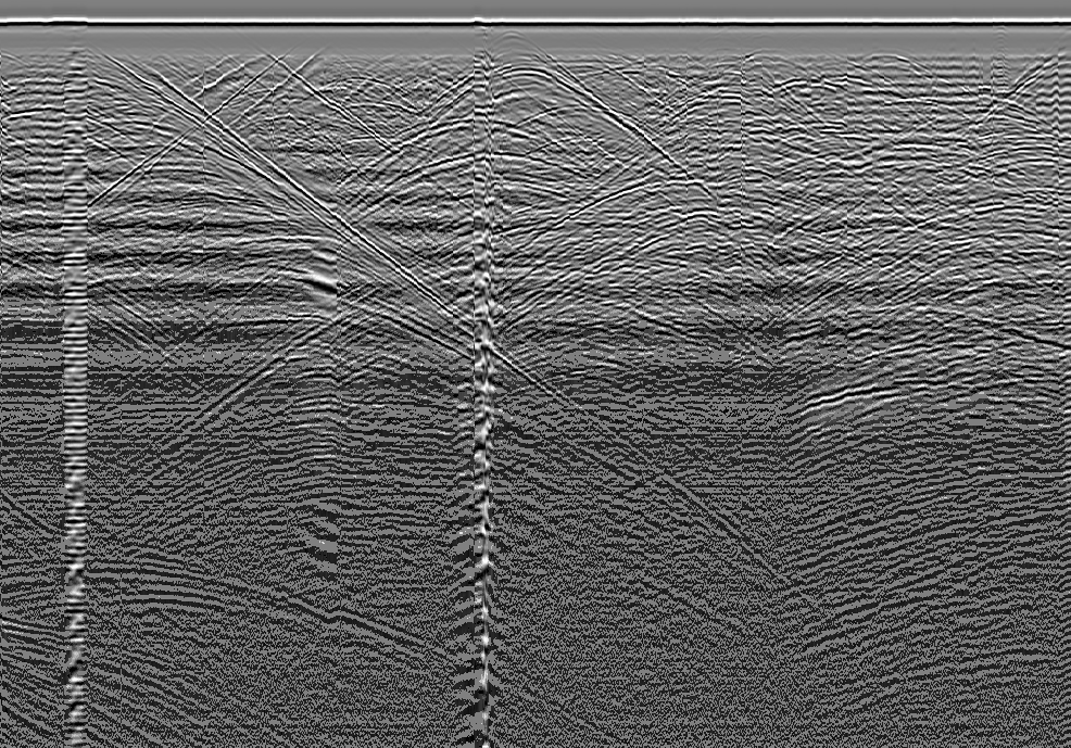
The granite spine (example 3) runs this chain end-to-end on the real Grimsel ISC
data (MALA GX160, AU and VE tunnels, CC-BY-4.0): with the granite_160 preset it
extracts 1472 picks on AU and 1485 on VE, at \(\mathrm{d}t=0.4464\,\mathrm{ns}\)
and \(\mathrm{d}x=0.0498\,\mathrm{m}\)
(examples/03_gpr_fracture_granite/README.md:14).
Originality.
FractureExtractoris evolved-fork. The high-energy + USGS-continuity base is clean-room from the cited literature (USGS Mirror Lake WRIR 99-4018C; Porsani 2006; Isakova 2021,GprFractureExtractComponent.cs:44). The dip-aware shear-count continuity that follows dipping shear zones while gating steep events is the measured delta over the flat-horizon USGS test. Fronted by GPR Fracture Extract (GUIDA7E0B0F1-0C0F-4A16-9E3D-0FACE0FACE02,GprFractureExtractComponent.cs:66),Exposure=secondary.
4.3.1 Stone-by-frequency presets¶
GprPresets holds the parameter sets that produced the validated 3-D models, one
per stone-type x antenna-frequency, with window sizes as fractions of the
trace sample count so a preset transfers across acquisitions (GprPresets.cs:7-25).
Two presets are empirically tuned on real data (marble_600 on Bondua Botticino,
granite_160 on Doetsch Grimsel); a granite frequency family (25-1200 MHz) and
the travertine / andesite / limestone presets carry paper-measured velocities but
extrapolated filter windows. The IsEmpirical flag records which is which so the
GH component can warn the user (GprPresets.cs:22-24, :86, :111). The marble
preset notably narrows the continuity span to 27 traces (\(\approx0.65\,\mathrm{m}\))
because marble fractures (stylolites, veins) are shorter than granite shear zones
(\(\approx0.9\,\mathrm{m}\) measured), surfacing marble's genuine short reflectors
from the same energy bar (GprPresets.cs:90-94).
Originality. clean-room parameter catalogue, no algorithm. The presets are calibration data; the
IsEmpiricalhonesty flag distinguishes validated from literature-default values.
4.4 From picks to surfaces¶
FractureSurface builds fracture surfaces from picks by two paths
(FractureSurface.cs:8-25). The managed loft path extrudes an ordered fracture
polyline along strike, or lofts adjacent parallel section-lines across a survey
grid onto a common X grid; the surface orientation follows the reflector
(sub-horizontal stays sub-horizontal, dipping stays dipping) rather than forcing a
vertical sheet (Loft, :42-70; LoftAcrossLines, :77-110). The reconstruct
path takes an unordered fracture point cloud and runs geogram screened-Poisson
(Kazhdan and Hoppe 2013) first, falling back to CGAL advancing-front for open
sheets (TryReconstructFromCloud, :112-139). The heavy 3-D reconstruction is
the only place this chapter touches a native shim, and it is optional with a clear
error when absent.
Originality. The loft path is clean-room elementary surface construction. The reconstruction path is wrapper-of-native over the geogram (BSD-3, with bundled Kazhdan PoissonRecon MIT) and CGAL (GPL) shims, reached out-of-process; only the dispatch is ours, and the CGAL route is quarantined per the licensing register.
4.5 The uncertainty ladder and safe yield¶
The deliverable is not a fracture surface, it is an honest fracture surface:
how far the reconstructed surface can deviate from the true fracture, propagated
through the pipeline, so a quarry can set a keep-out margin and pack blocks only
into provably-intact rock. FractureUncertainty is that tolerance ladder
(FractureUncertainty.cs:6-33). The per-location 1-sigma position uncertainty
combines three independent contributions in quadrature:
Reconstruction sigma (original derivation). The GPR time-to-depth conversion \(\mathrm{depth}=v\,t/2\) with \(v=c/\sqrt{\varepsilon_r}\) has three error sources. First, a relative velocity error that grows with depth: differentiating \(v\propto\varepsilon_r^{-1/2}\) gives
so the depth term is \(\mathrm{depth}\cdot\sigma_v/v\) (VelocityRelUncertainty,
:48-53). Second, the vertical-resolution floor \(\lambda/4\), with
\(\lambda/4=v/(4f)\) (LambdaQuarter, :39-45). Third, the time-zero pick
ambiguity \(v\,\sigma_{t_0}/2\), where the first-break-to-first-apex window is a
rectangular distribution \(\sigma_{t_0}=(t_{\text{apex}}-t_{\text{break}})/(2\sqrt3)\)
(TimeZeroSigma, RectTimeZeroSigma, :55-65). The combined reconstruction
sigma is
The velocity term leads at quarry depth (Porsani 2006 reports
\(\pm8.5\text{-}9.5\%\) at 25 m); the time-zero term leads near the surface (Xie,
Lai and Derobert 2021); \(\lambda/4\) is a floor, not the dominant term
(DepthSigma, :67-81). Passing \(\sigma_{t_0}=0\) reproduces the original
two-term form, so the time-zero rung is an additive evolution of the earlier
ladder (:67-72).
Interpolation sigma. Between scan lines the surface is interpolated, and the
interpolation has its own uncertainty: zero at a pick, growing in the gaps. This
is supplied by the kriging posterior standard deviation. The Kriging class is
simple kriging on mean-centred data with a Gaussian covariance
\(C(h)=\text{sill}\cdot e^{-(h/\text{range})^2}\) and a nugget; the posterior
variance at a query point is
i.e. the prior variance minus what the data explain, via the Cholesky factor
(Kriging.cs:19-29). It is the managed replacement for the prototype's
scikit-learn GaussianProcessRegressor, exact and shim-free because kriging is
linear algebra (Cressie 1993; Rasmussen and Williams 2006).
Mesh sigma. The triangulation cuts the true curved surface by the chord
sagitta, \(\sigma_{\text{mesh}}=(h^2/8)\,\kappa\) for edge length \(h\) and curvature
\(\kappa\) (MeshSigma, :83-85).
The confidence metric. The optimisation target is not sigma itself but the confidence: the probability that the fracture lies within a fabrication tolerance \(T\), assuming a zero-mean Gaussian deviation,
averaged over the surface (ConfidenceWithin, :95-100). The error function is
the Abramowitz-Stegun 7.1.26 rational approximation (\(|\text{error}|<1.5\times10^{-7}\)),
again to avoid a MathNet dependency (Erf, :222-230). Lowering sigma (calibrate
velocity, denser scan lines, higher frequency, finer mesh) raises confidence; the
ladder quantifies each trade.
The detection rung (original derivation). A position sigma only matters for a
fracture that is seen. A missed fracture has no sigma but is the real yield
risk, so the ladder adds a detection model grounded in the imaging literature
(Molron et al. 2020 Aspo; Dorn et al. 2012). The minimum detectable area is
Fresnel-zone limited and grows with depth, \(A_{\min}\approx(\lambda/4)\cdot
\mathrm{depth}/2\) above a shallow resolution floor (MinDetectableArea,
:111-128). The detection probability factorises over dip, aperture, and size:
with \(\eta\) the imaging ceiling (\(\approx0.80\) open, Molron; \(0.91\) transmissive,
Dorn), \(p_{\text{dip}}=1\) for sub-horizontal fractures smoothstepping to \(0.1\) by
\(75^\circ\) (surface GPR poorly images sub-vertical fractures), and a sealed-factor
penalty for mineral-filled fractures (DetectionProbability, :130-150). The
effective confidence caps position confidence by detection completeness,
\(C_{\text{eff}}=P_{\text{det}}\cdot\textsf{confidence}\), so a low detection
probability limits trust however precisely the seen fractures are located
(EffectiveConfidence, :152-160; Summarise, :191-220).
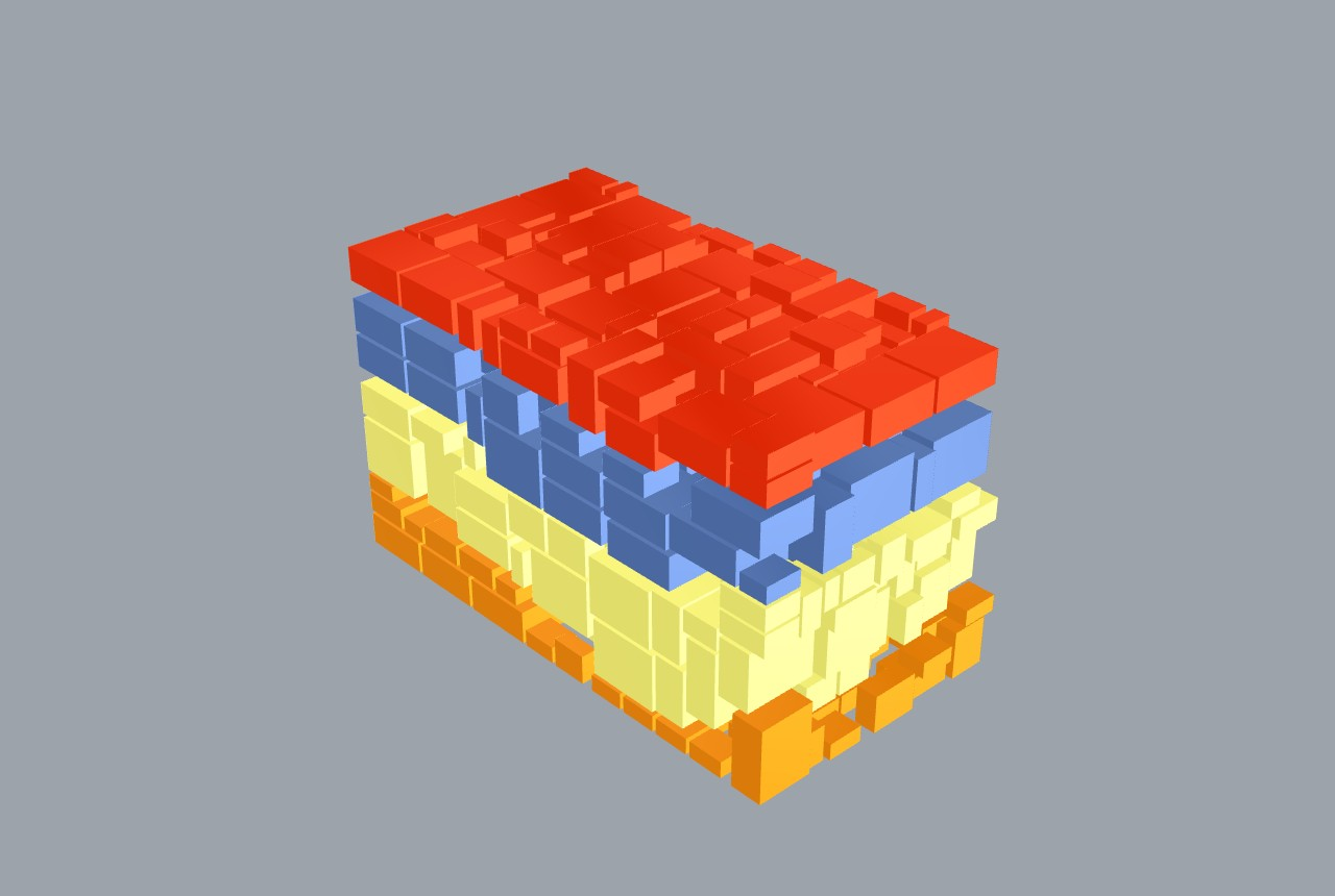
Example 9 is the full quarry decision. The GPR fracture surfaces (from the granite
spine) bound the intact zones; Fracture Block Pack (GUID
A7E0B0F3-0C0F-4A16-9E3D-0FACE0FACE04) packs fixed-size dimension blocks into
each zone with an inward Fracture Clearance wired to the GPR position sigma,
so no block sits within the measured uncertainty of a fracture. Toggling
uncertainty-safe off gives the optimistic geometric yield; on gives the
uncertainty-safe yield (FractureBlockPackComponent.cs:10-25;
examples/09_uncertainty_safe_yield/README.md:12-17).
Originality.
FractureUncertaintyis original-research (A-candidate). The three-rung position ladder, the depth-growing velocity term plus time-zero plus \(\lambda/4\) decomposition, and the detection rung with the depth-aware Fresnel floor and the \(P_{\text{det}}\) factorisation are the Frahan contribution; the underlying physics is cited (Porsani 2006; Xie 2021; Molron 2020; Dorn 2012).Krigingis clean-room ordinary kriging (Cressie 1993; Rasmussen and Williams 2006). The surface-and-ladder front end is GPR Fracture Surfaces 3D (GUIDA7E0B0F2-0C0F-4A16-9E3D-0FACE0FACE03,GprFractureSurface3DComponent.cs:30), which clusters the pick cloud, kriges each fracture, and colour-maps \(\sigma_{\text{total}}\) green-to-red.
4.6 RecoveryCascade: multi-scale crack-aware recovery¶
The fracture map feeds the block-cutting solver of chapter 3, but a single-scale
packer discards every block a fracture crosses. RecoveryCascade recovers value
from those blocks by running the cutter at progressively finer scales: at each
scale BlockCutOpt is solved on the region, the non-intersected blocks are
recovered, and every cracked block is fed back into the same engine at the
next finer scale, cutting around the fracture, until the remnant falls below the
smallest marketable size (RecoveryCascade.cs:9-37).
Original derivation: the recovery recursion. The value recovered from a tested region \(R\) at scale \(s\) is
where the kept / cracked partition of the winning grid is decided by
!bvh.AnyTriangleIntersects against a single shared immutable fracture BVH
(RecoveryCascade.cs:25-29, :91-119). The recursion depth is capped at the
number of scales, so it cannot run unbounded (:74). Crucially, with a single
ScaleSpec the cascade recovers exactly the non-intersected blocks
BlockCutOptSolver.Solve finds, with the same winning pose and the same
intersection predicate, so it reduces to BlockCutOpt 2020 exactly at scale 1
and is a faithful superset (:21-24). It is grounded in the conditional
two-scale (Yarahmadi 2018), usable-leftover (Cherri 2009), and staged-guillotine
(Gilmore and Gomory 1965) literatures.
Originality.
RecoveryCascadeis evolved-fork. The 3-D recursive reject-recover cascade extends the single-scale BlockCutOpt baseline (chapter 3) to which it provably reduces. The header now credits the companion paper (Murugean 2026) for the unified cascade rather than self-labelling "novel"; the earlier unsoftened "novel" wording was flagged E9 in the originality audit (docs/thesis/90_originality.md:188). No GH consumer wires it yet (see Status). The separateFractureBlockPackGH component is a facade-over-primitives self-contained recovery engine that does not callRecoveryCascade, a silent-disagreement risk also tracked in the register.
4.7 Earthworks: bedrock surface and the overburden strip¶
The same GPR picks lift a bedrock surface for the overburden strip. The
deepest continuous strong reflector below the weathered cover is the top of fresh
rock (Porsani profiles; Bondua bedrock). BedrockSurface.DeepestReflectorPoints
reduces a pick set to the deepest qualifying reflector per \((x,y)\) column and
converts depth to world elevation \(z_r=z_{\text{ground}}(x,y)-\mathrm{depth}\)
(BedrockSurface.cs:7-19, :51-93). The picks come from one or more survey
lines, scattered in \((x,y)\).
TinMerge.ResampleOntoVertices fuses those sparse bedrock picks onto the dense
ground TIN so a downstream prism-difference can compute the overburden volume,
because that consumer requires both surfaces sampled on the same
triangulation (TinMerge.cs:8-27). It resamples by k-nearest inverse-distance
weighting (Shepard 1968):
over the k nearest source picks within a scale-relative radius (a multiple of
the median source spacing), with a uniform-grid spatial index, and flags target
vertices with no source inside the radius as NaN so the caller can clip them
(TinMerge.cs:54-122). Coordinates are recentered first so UTM / quarry-scale
\((x,y)\) do not lose mantissa precision (the GeometryNumerics T1 rule, :20-23).
TinPeelFilter is the upstream scan-cleaner. A raw Delaunay or Poisson
reconstruction fills the whole convex hull, so concave shorelines and data gaps
grow long thin cap triangles and near-vertical gap webs that are not real
terrain. The filter iteratively peels border triangles satisfying any of three
predicates, then drops connected components below a minimum size
(TinPeelFilter.cs:7-29): a long edge \(\max(e_0,e_1,e_2)^2>(k\,m)^2\) where
\(m\) is the median 2-D edge and \(k=3\) aggressive / 10 careful; a near-vertical
facet with normal tilt \(>85^\circ\); and a cap / sliver with an interior
angle opposite the border edge \(>140^\circ\) (:18-23, ShouldPeel, :139-163).
The thresholds are relative to the local median edge, so the same filter works at
any survey scale (the scale-relative-epsilon principle).
Originality.
TinPeelFilteris clean-room (the border-peel logic ported from the Fade2D land-survey reference'speelOffIf, no upstream code, cited in the Clean Scan Mesh[Algorithm],CleanScanMeshComponent.cs:29-31, GUIDA7E0B0F1-0C0F-4A16-9E3D-0FACE0FACE03).TinMergeis clean-room k-NN IDW (Shepard 1968) with a scale-relative radius.BedrockSurfaceis clean-room: pure reduction and datum shift, no FFT. The bedrock front end is GPR Bedrock Surface (GUIDA7E0B0F1-0C0F-4A16-9E3D-0FACE0FACE04,GprBedrockSurfaceComponent.cs:33-35, citing Porsani 2006 / Isakova 2021 for the top-of-rock reflector and Shepard 1968 for IDW).
4.8 The vector counterpart: surface fracture maps¶
GPR sees fractures with depth; a shapefile carries the mapped surface trace
network, the cheapest fracture data a quarry has (drone photo plus tracing).
Example 26 reads a real ESRI Shapefile of Loviisa rapakivi-granite fracture traces
through the Frahan > Quarry > Ingestion vector reader and renders the strike map.
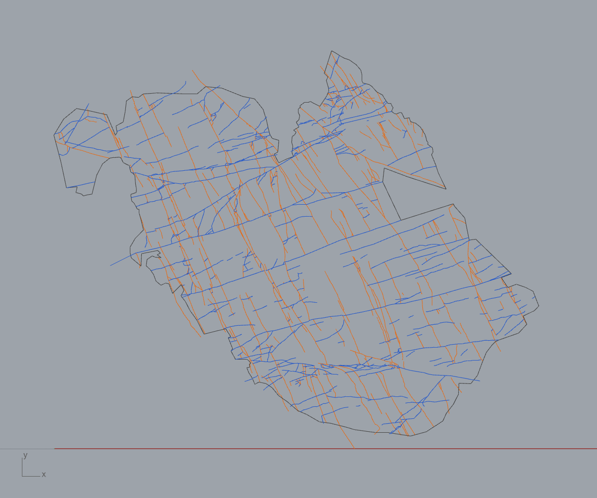
The reader returns 708 traces / 6483 vertices, total length 1593.5 m, CRS
EUREF_FIN_TM35FIN (EPSG:3067), with two conjugate sets peaking at \(\approx15^\circ\)
(NNE) and \(\approx105\text{-}120^\circ\) (ESE) (Chudasama 2022, CC-BY-4.0;
examples/26_loviisa_surface_fractures/README.md:26-30). The strike histogram is
the input a quarry needs to orient block cuts away from the dominant joint set,
and combined with a GPR depth survey it constrains the 3-D intact-block volume.
Originality. vendored-library reader (NetTopologySuite.IO.Esri, ESRI Shapefile / OGC Simple Features); the strike binning and rendering are clean-room, no new algorithm.
4.9 Status & what's left¶
- Example 3 figure is a radargram, not the extracted-pick overlay. The folder
ships
03_gpr_radargram_AU.png(the migrated section) plus the two.ghcanvases, but no rendered fracture-pick / 3-D surface PNG; the README marks the example "pending live regeneration" with repath, stage groups, and a shaded viewport capture still to do (examples/03_gpr_fracture_granite/README.md:22-26). Severity: medium (documentation / figure gap, the chain itself is validated to the 1472 / 1485 pick counts). RecoveryCascadehas no GH consumer. The recursion is implemented and tested in Core but no canvas component wires it, and the shippedFractureBlockPackcomponent runs its own self-contained recovery engine instead, a silent disagreement risk if the two diverge (docs/thesis/90_originality.md:66,:68). Severity: high..gsfis read-only via conversion. Geoscanners AKULA stays unsupported by design; the user must export to SEG-Y with GPRSoft or RGPR first (GprFileReader.cs:46-51). This blocks any dataset that ships only.gsf. Severity: medium (a real Tamil Nadu charnockite data path depends on it).- Literature-default presets are unvalidated end-to-end. Only
marble_600andgranite_160areIsEmpirical=true; the granite frequency family and the travertine / andesite / limestone presets carry paper velocities but extrapolated filter windows (GprPresets.cs:22-24,:110-111). The component warns, but a user running an unvalidated preset gets uncalibrated continuity spans. Severity: medium. - Reconstruction path needs native shims.
TryReconstructFromCloudreturns a clear error when geogram / CGAL are absent, and the CGAL route is GPL, quarantined out-of-process (FractureSurface.cs:131-138; licensing register E3/E4). The default install has no reconstruction; loft-only surfaces are the fallback. Severity: low (managed loft path covers the common ordered-line case). - AABB child region in the cascade is exact only for axis-aligned blocks.
AabbOfis exact for psi-only (axis-aligned) oriented blocks; a fully tilted pose feeds the finer scale a slightly loose axis-aligned bound (RecoveryCascade.cs:122-123). Severity: low (conservative, never drops a real block).
References (this chapter)¶
- Stolt, R.H. (1978). Migration by Fourier transform. Geophysics 43(1):23-48. DOI 10.1190/1.1440826. [R146]
- Taner, M.T., Koehler, F., Sheriff, R.E. (1979). Complex seismic trace analysis. Geophysics 44(6):1041-1063. DOI 10.1190/1.1440994. [R147]
- Cooley, J.W., Tukey, J.W. (1965). An algorithm for the machine calculation of complex Fourier series. Mathematics of Computation 19(90):297-301. DOI 10.1090/S0025-5718-1965-0178586-1.
- Porsani, J.L., Sauck, W.A., Junior, A.O.S. (2006). GPR for mapping fractures and as a guide for the extraction of ornamental granite from a quarry. Journal of Applied Geophysics 58:177-187. DOI 10.1016/j.jappgeo.2005.05.010. [R34]
- Molron, J., Linde, N., Baron, L., Selroos, J.O., Darcel, C., Davy, P. (2020). Which fractures are imaged with ground penetrating radar? Engineering Geology 273:105674. DOI 10.1016/j.enggeo.2020.105674. [R36]
- Dorn, C., Linde, N., Doetsch, J., Le Borgne, T., Bour, O. (2012). Fracture imaging within a granitic rock aquifer using multiple-offset single-hole and cross-hole GPR reflection data. Journal of Applied Geophysics 78:123-132. DOI 10.1016/j.jappgeo.2011.01.010. [R37]
- Xie, F., Lai, W.W.L., Derobert, X. (2021). GPR-based depth measurement of buried objects based on constrained least-square fitting. Measurement 168:108330. DOI 10.1016/j.measurement.2020.108330. [R41]
- Annan, A.P. (2009). Electromagnetic principles of ground penetrating radar. In: Jol, H.M. (ed.) Ground Penetrating Radar: Theory and Applications. Elsevier, pp 3-40. [R39]
- Neal, A. (2004). Ground-penetrating radar and its use in sedimentology. Earth-Science Reviews 66:261-330. DOI 10.1016/j.earscirev.2004.01.004. [R40]
- Bondua, S., Monteiro Klen, A., Pilone, M., Asimopolos, L., Asimopolos, N.S. (2024). A set of ground penetrating radar measures from quarries. Data 9(3):42. DOI 10.3390/data9030042. [R44]
- Huber, E., Hans, G. (2018). RGPR — an open-source package to process and visualize GPR data. 17th International Conference on GPR, IEEE. DOI 10.1109/ICGPR.2018.8441658. [R43]
- Lucius, J.E., Powers, M.H. (1999). USGS Open-File Report 02-166: GPR data-format documentation (pulseEKKO DT1/HD spec). [R45]
- Shepard, D. (1968). A two-dimensional interpolation function for irregularly-spaced data. Proc. 23rd ACM National Conference, pp 517-524. DOI 10.1145/800186.810616.
- Cressie, N.A.C. (1993). Statistics for Spatial Data. Wiley. DOI 10.1002/9781119115151. [R119]
- Rasmussen, C.E., Williams, C.K.I. (2006). Gaussian Processes for Machine Learning. MIT Press. DOI 10.7551/mitpress/3206.001.0001. [R120]
- Kazhdan, M., Hoppe, H. (2013). Screened Poisson surface reconstruction. ACM Transactions on Graphics 32(3):29. DOI 10.1145/2487228.2487237. [R91]
- Yarahmadi, R., Bagherpour, R., Taherian, S.G., Sousa, L.M.O. (2018). Discontinuity modelling and rock block geometry identification to optimize production in dimension stone quarries. Engineering Geology 232:22-33. DOI 10.1016/j.enggeo.2017.11.006. [R20]
- Cherri, A.C., Arenales, M.N., Yanasse, H.H. (2009). The one-dimensional cutting stock problem with usable leftover. European Journal of Operational Research 196:897-908. DOI 10.1016/j.ejor.2008.04.039. [R12]
- Gilmore, P.C., Gomory, R.E. (1965). Multistage cutting stock problems of two and more dimensions. Operations Research 13:94-120. DOI 10.1287/opre.13.1.94. [R11]
- Chudasama, B. (2022). Loviisa rapakivi-granite fracture and lineament dataset, southern Finland. Zenodo, CC-BY 4.0. [R53]
- Murugean, L. (2026). GPR-to-block-yield optimization for fractured dimension-stone quarries (submitted, Bulletin of Engineering Geology and the Environment; reproducibility deposit). DOI 10.5281/zenodo.20608279. [R144]
- USGS (1999). Mirror Lake GPR continuity protocol, Water-Resources Investigations Report 99-4018C (>=40-trace lateral-continuity criterion).
- Isakova, E. (2021). GPR survey of fractured Karelia granite (OKO-2, 150 / 1200 MHz antennas).
05. Masonry Equilibrium & Cyclopean Reassembly (CRA)¶
The Masonry tab (ribbon Frahan > Masonry, 35 components) covers the
stone-on-stone end of the repository: turning a set of blocks into a wall, a
wall into a verified static structure, and an inventory of found stones into a
fitted, carved assembly. The subsystem has three layers. The lowest is a
managed reimplementation of Coupled Rigid-Block Analysis (CRA) and its
Rigid-Block Equilibrium (RBE) precursor, ported from the published
mathematics of Kao et al. (2022) and structured after the MIT BlockResearchGroup
compas_cra reference. Above it sit the convex solvers (a managed QP, an
OSQP-style ADMM, and a kinematic certificate search). On top of both sit the
generation and assignment layer: a polygonal-wall generator, an exact-joint
assembler, the imposition metric Lambda, and the Cyclopean carve-back.
Provenance in one line: the equilibrium and friction algebra is clean-room
from a cited paper; the CRA verdict is built from an A-candidate convex
certificate that is not in the upstream; the generator and Lambda metric are
A-candidate original-research; the rubble settle is clean-room from robotics
sources; and the assignment/carve-back are facade compositions of in-repo
primitives. Every claim below is anchored to file:line, an [Algorithm]
attribute, or a test.
The static-analysis truth criterion for this chapter is the battery: at the
last audit the suite reported 1034 PASS / 0 FAIL, including the CRA H-model
counterexample regression and a compas_cra cross-fixture parity set
(tests/Frahan.StonePack.Tests/Program.cs:334, :347-:356).
5.1 Rigid-block equilibrium (RBE)¶
The equilibrium matrix¶
A masonry assembly is a set of rigid blocks meeting at planar interfaces. Each interface carries a contact polygon whose vertices each host a contact force resolved on a local frame: one normal \(\mathbf{n}\) (block A into block B) and two tangents \(\mathbf{t}_1,\mathbf{t}_2\). For block \(i\) with centre of mass \(\mathbf{c}_i\), static equilibrium under self-weight \(\mathbf{W}_i\) is force and moment balance summed over every incident interface and every contact vertex \(k\) at world position \(\mathbf{r}_k\):
Gravity acts at the centre of mass, so \(\mathbf{M}^{W}_i = \mathbf{0}\). Stacking
the six rows (three force, three moment) for every free block, and one column
per contact-vertex force component, gives the linear system the code builds
verbatim (EquilibriumMatrixBuilder.cs:13-30):
The per-column contribution is a force triple and the cross-product moment
triple \((\mathbf{r}_k - \mathbf{c}_i) \times \mathbf{e}\) for each basis vector
\(\mathbf{e}\in\{\mathbf{n},\mathbf{t}_1,\mathbf{t}_2\}\), written explicitly at
EquilibriumMatrixBuilder.cs:201-219. Sign convention follows
compas_cra/equilibrium/cra_helper.py: block A sees \(+1\), block B sees \(-1\)
(:113-121). Fixed blocks contribute no rows (:158-162). The gravity load is
\(b[F_z]=\rho V g_z\) with \(g_z=-9.80665\,\mathrm{m/s^2}\) (:127-138,
:44). A penalty variant splits the normal into a \(f_n^{+}/f_n^{-}\) pair
(shift 4 instead of 3) so a tensile residual can be measured rather than
forbidden (:79-92).
The friction cone and its linearisation¶
Coulomb friction at each contact is the second-order cone
RBE replaces it with a polyhedral pyramid of \(K\) faces. Face \(k\) at angle \(\theta_k = 2\pi k/K\) contributes the linear row
assembled into \(A_{fr}\tilde f \le \mathbf 0\) (FrictionConeBuilder.cs:24-32,
:236-251). The default \(K=4\) is special-cased to exact
\(\{+1,0,-1,0\}\) coefficients to match compas_cra._make_afr bit-for-bit
(:215-227); \(\mu=0.84\) (a 40-degree friction angle) is the upstream default
(:83-86).
Original derivation: the inscribed-pyramid correction. A circumscribed square pyramid over-estimates the cone. Its faces touch the cone along the axes but bulge out at \(45^\circ\), where the admissible tangential magnitude is
which at \(K=4\) equals \(\mu f^n / \cos 45^\circ = \sqrt 2\,\mu f^n\): the linearisation grants up to \(\sqrt 2 \approx 1.41\) times the true friction capacity. For a stability claim that is the wrong direction (it certifies unstable walls as stable). The fix is to shrink the coefficient so the pyramid is inscribed in the cone,
making every admissible \((f^{t_1},f^{t_2})\) satisfy the exact quadratic cone, a
conservative under-approximation (FrictionConeBuilder.cs:105-130). The CRA
checker passes inscribed: true by default (CraStabilityChecker.cs:90); the
flag was a flagged correctness gap (the V3-review blocker) and is the
recommended setting for any published verdict.
The QP and the verdict¶
RBE is then a convex quadratic program (RbeQpFormulation.cs:11-19):
\(H\) is diagonal with separate normal and tangential weights; the default
identity recovers the minimum-norm contact-force solution, and a tangential
weight of \(\sim10^3\) (Kao 2022 section 5) biases toward normal-dominated
distributions (:78-111). The \(f^n\ge0\) box enforces compression-only
contact (:140-166). Feasibility of this QP is the stability verdict: a
feasible force state means a statically admissible solution exists.
Sign fix. The original Build set the equality right-hand side to \(-\mathbf b\),
which combined with the builder's \(A_{eq}[F_z]=-1\) and \(b[F_z]=-mg\) yields
\(f^n=-mg<0\), infeasible against \(f^n\ge0\). BuildPhysicsCorrected flips the sign
so \(f^n\ge0\) means compression (RbeQpFormulation.cs:180-224). The shipped GH
component calls BuildPhysicsCorrected, not the legacy Build, with the bug
explained inline (MasonryStabilityRbeComponent.cs:297-305); the prior audit
note that the component still wires the sign-buggy Build is stale for the
current source.
Originality. RBE is clean-room (tier B). The implementation is a
pure-managed transcription of the equations in Kao et al. (2022), with the MIT
compas_cra reference as the structural model (cited at
MasonryStabilityRbeComponent.cs:69-71; GUID
F6BAC3D4-4E5F-4071-BC3D-5E6F7A8B9CAD). No upstream .cs is in the tree; the
parity tests compare numbers, not lines (CraCompasParityTests). The
inscribed-pyramid correction is the small clean-room delta over a naive
transcription.
5.2 Coupled Rigid-Block Analysis (CRA)¶
RBE is force-only, and force-only equilibrium admits physically unrealisable
states. Kao's H-model is the canonical counterexample: a beam bridging two
columns, touching them only on vertical faces with nothing underneath. RBE
finds a self-equilibrated horizontal squeeze whose friction carries the beam,
even though nothing can produce that squeeze. CRA couples statics with virtual
rigid-body kinematics so that contacts only carry force where a consistent
motion lets them engage (CraStabilityChecker.cs:17-50). The coupling
conditions (Kao 2022 Eqs. 8-11) are
The exact problem is a nonconvex NLP (bilinear complementarity); compas_cra
solves it with IPOPT. The repository does not ship IPOPT. Instead it
implements an alternating convex certificate search that is sound in the
certifying direction (:31-49):
- Solve the penalty RBE QP for forces \(f\).
- Solve a convex kinematic certificate QP: given the engaged set \(E=\{k: f^n_k > \text{tol}\}\) and the friction directions \(\hat f_t\), find a virtual motion \(\delta q\) and slacks \(\beta\ge0\) minimising
$$ \sum_{k\in E}!\left(\frac{\delta d_{n,k}-\varepsilon}{\varepsilon}\right)^2 + \sum_{k}!\left(\frac{\delta d_{t,k}+\beta_k\hat f_{t,k}}{\varepsilon}\right)^2 $$
subject to \(\delta d = A_{eq}^{\top}\delta q\), non-penetration
\(s\,\delta d_n\le\varepsilon\), and a virtual-motion bound \(|\delta d|\le\eta\)
(:236-240). A near-zero residual means a consistent virtual motion exists,
so the state is CRA-certified.
3. Otherwise restrict: contacts whose engagement the kinematics rejected
have their normal columns forced to zero (complementarity, Eq. 10),
badly misaligned friction is zeroed (Eq. 9), and the force QP is re-solved.
Tension or infeasibility means the RBE acceptance was self-stress, so the
assembly is CRA-unstable.
4. Iterate, bounded (:127, maxOuterIterations=12).
A found \((f,\delta q,\alpha\ge0)\) triple is a feasible point of the CRA
constraints, so "certified" is sound; "not certified" is conservative because
the alternating search is a heuristic for a nonconvex problem (:45-49). Two
engineering refinements matter for correctness. The engagement threshold is set
to 1% of peak normal force so min-norm RBE's tiny spurious forces on
load-free joints are not treated as engaged (:131-138). Engagement weighting
is force-weighted, \(w_i=\sqrt{f^n_i/f^n_{\max}}\), mirroring the NLP's energy
trade where unloading a lightly-loaded joint is cheap (:255-263). The
certificate has an exact fast path: solve the unconstrained least squares by
dense Cholesky (SolveDenseSpd, :412-444), and only fall back to the
constrained ADMM (warm-started at the LS optimum) when the LS point violates
non-penetration (:342-384).
Original derivation: the residual decode. The certificate solves
\(H = 2J^{\top}J\), \(c = 2J^{\top}r_0\), i.e. the normal equations of the
weighted least-squares system \(J x + r_0\) with \(x=[\delta q,\beta]\)
(:289-306). The reported residual is the worst force-weighted engaged-vertex
mismatch in units of \(\varepsilon\),
with the certified threshold at \(0.5\varepsilon\) (:181-186, :387-396). The
restriction peels only the worst offenders each round (within 75% of the worst
weighted residual) so de-loading mirrors the exact NLP's energy trade
(:189-201).
Originality. The CRA verdict is an A-candidate (original formulation,
prior-art sweep pending). The equations are Kao's, but the
alternating-convex soundness certificate is not in compas_cra, which uses a
nonconvex IPOPT solve. The contribution is the managed soundness certificate,
not the algorithm family. It is fronted by the Masonry Stability Check
component (GUID D5F10015-2B43-4E8A-A1C7-9D0F4B6E2A91,
MasonryStabilityCheckComponent.cs:34). The H-model is a first-class
regression test: Cra_HModel_RbeAcceptsButCraRejects asserts RBE accepts and
CRA rejects (CraStabilityCheckerTests.cs:83-105), and a compas_cra
cross-fixture parity suite pins agreement on shared cubes, stacks, and an arch
(Program.cs:347-356).
5.3 The convex solvers (ADMM)¶
The certificate's constrained fallback and the penalty RBE QP run on a
pure-managed OSQP-style ADMM solver (AdmmQpSolver.cs:6-51). The standard form
is
with equality, inequality, and box-bound blocks stacked into one CSR matrix \(A\). The iteration (Stellato et al. 2020, simplified) is
with the factorisation cached and refactored only on \(\rho\) changes
(:182-256). Convergence is the standard primal/dual infinity-norm test
(:224). Two adaptations tame the masonry systems, which mix newton-scale
forces, metre-scale moment arms, and the \(10^3\) penalty weight: full Ruiz
equilibration of rows and columns over three passes
(:108-145), and per-row \(\rho\) that stiffens equality rows by \(10^3\)
(:475-478). The constraint blocks are >99% sparse, stored CSR for \(O(\text{nnz})\)
matvecs (:36-39, :318-426).
A measured limit is recorded honestly: cold-start convergence on penalty-RBE
systems degrades past about 50 contact interfaces (54-interface wall 5.4 s,
147-interface 86 s), which is why MasonryStabilityChecker runs an LS-first
KKT certificate that decodes wall verdicts without ADMM and only falls back to
the warm-started solver when the certificate declines
(AdmmQpSolver.cs:41-50).
Originality. The ADMM is clean-room (tier C): a faithful, simplified OSQP from Stellato et al. (2020), with masonry-specific equilibration and per-row \(\rho\) as engineering deltas. It is solver infrastructure, not a research contribution.
5.4 The polygonal wall generator (v2)¶
The generator builds an architectural polygonal-masonry pattern in the
\((u,v)\) parameter rectangle and reports a quality score
(PolygonalWallGenerator.cs:7-34; component GUID
D5F10014-7A11-4C0E-9B22-3F6A1E2C4D80, PolygonalWallGeneratorComponent.cs:37).
Four pieces of math compose it.
Power diagram. Cells are an additively-weighted Voronoi diagram of jittered-grid seeds, computed exactly by half-plane clipping:
where per-seed weights \(w_i\) give genuine size grading (:13-17). The method
is \(O(n^2 v)\), exact, and bounded for the few-hundred stones a wall needs.
Lloyd relaxation moves seeds to cell centroids over \(k\) iterations to even
size and roundness (:18-19, Lloyd 1982). Coursing morph interpolates each
vertex toward its nearest course line,
a continuum from \(c=0\) irregular (Inca) to \(c=1\) coursed rubble (:20-21).
Sliver cull removes cells whose inradius proxy \(\rho = 2A/P\) falls below
\(\text{frac}\cdot\sqrt{WH/n}\) and recomputes the diagram (:22-24).
Original derivation: the interlock score \(J\). The generator reports an
interlock quality \(J\in[0,1]\) formalising the Inca reading of Clifford and
McGee's (2018) shape-grammar analysis (:25-30, InterlockScore,
:310-384). Head joints are interior, more-vertical-than-horizontal cell
edges (:341-345); two head joints in consecutive courses are aligned (a
running joint, the masonry failure mode) when their \(u\)-midpoints coincide
within tolerance (:360-375); a cross vertex is a diagram node where four or
more cells meet, a "+" junction that weakens interlock (:377-379). The score
penalises both:
with each interior edge counted twice (once per neighbour) and halved
consistently (:350-353, :374, :381-383). Higher \(J\) means better
staggering.
Originality. A-candidate original-research. Kim (2024) does masonry
sequencing, not generation; the Coursing-morph continuum and the \(J\) metric
have no local-corpus equivalent (prior-art sweep pending, Legakis et al. 2001
closest). The GH hover credits Kim 2024 as the sequencing substrate, Clifford
and McGee 2018 for the interlock reading, and Lloyd 1982 for relaxation
(PolygonalWallGeneratorComponent.cs:31-33).
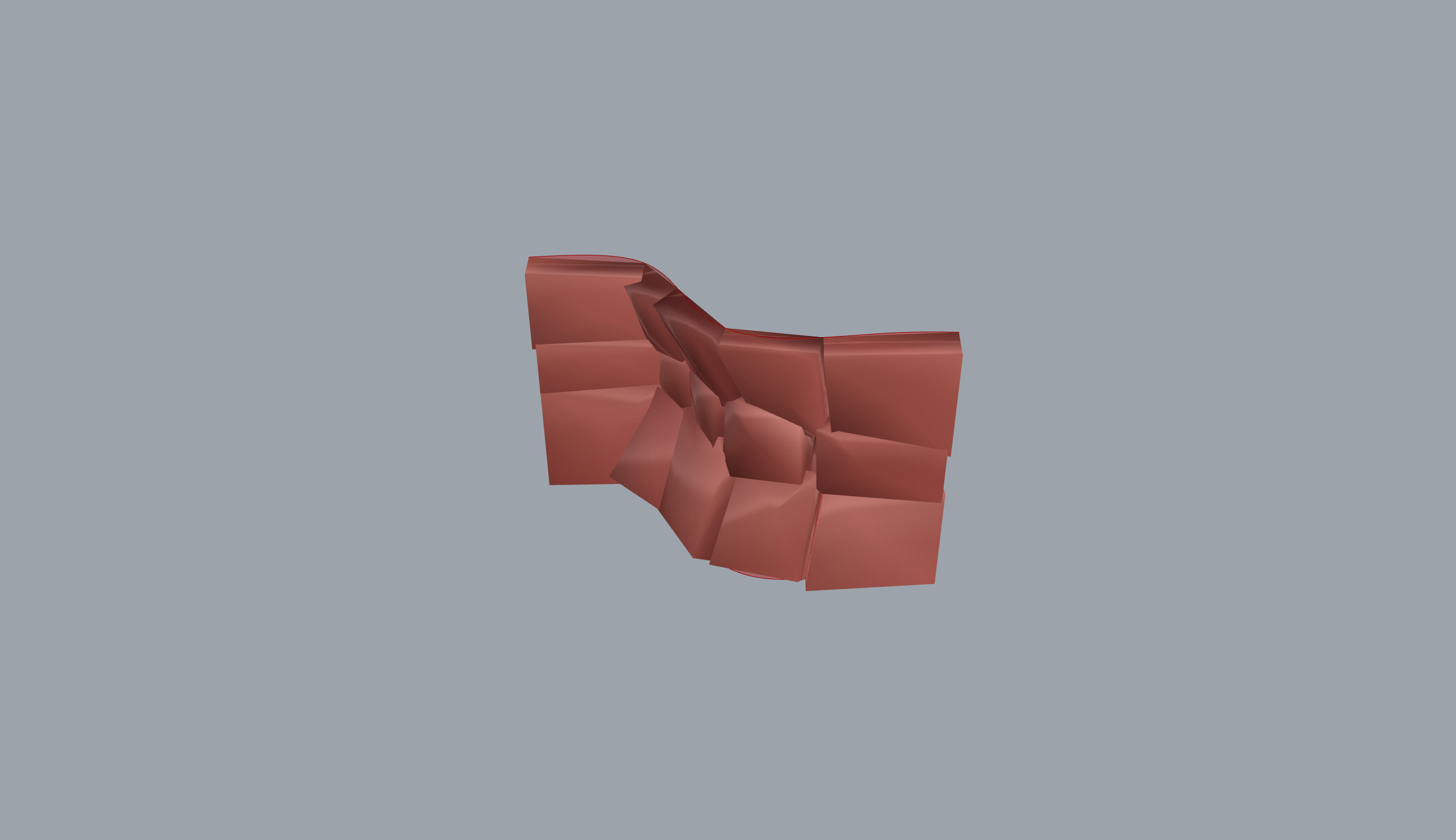
5.5 The exact-joint assembler¶
The generator already knows cell adjacency (shared power-diagram edges), so
re-detecting contacts from triangle meshes is wasteful and lossy: a mesh
contact detector splinters 40 stones into ~125 sub-interfaces and ~612 contact
vertices, inflating and ill-conditioning the QP. PolygonalWallAssembler emits
one exact planar-quad interface per adjacent stone pair directly from the
shared \((u,v)\) edge (PolygonalWallAssembler.cs:8-30):
Because stones are extruded per-vertex along the surface normal, both stones
build their side walls from the same two rails, so the quad is exactly the
shared face on any curvature with zero tolerance dependence. This is the
correct input to the equilibrium builder of 5.1, which is why CRA certifies
generated walls (Cra_GeneratedWall_Certified, Program.cs:335).
Originality. clean-room (tier B) geometry: the quad construction is elementary, and the contribution is the lossless coupling of generator adjacency to the equilibrium QP rather than any new algorithm.
5.6 The imposition metric Lambda and Cyclopean carve-back¶
The assignment layer makes the top-down/bottom-up balance executable. Given a
stone inventory (found/scanned stones, the negotiation side) and the
target cells of a generated wall (the imposition side), assign stones to
cells minimising the material to carve away, and report the trade as numbers
(StoneCellAssignment.cs:8-37):
\(\Lambda\approx1\) is full imposition (stock cut entirely to cells, sawn ashlar);
\(\Lambda\approx0\) is true negotiation (stones used as found). The measured
middle is Clifford and McGee's Cyclopean Cannibalism wall at \(\Lambda\approx0.27\)
(73% of scanned stock used), the datum the ETH1100 benchmark test reports
against (StoneCellAssignmentEthBenchmarkTests.cs:14, :95). The reported
result on ETH1100 is \(\Lambda=0.194\) (better than the 0.27 datum).
The pipeline is: per-mesh volume/centroid/PCA frame; a cheap volume+extent
prefilter; a voxel symmetric-difference cost over the top-K candidates per cell,
best of the four proper-rotation flips (:283-335); a Hungarian one-to-one
assignment reused from Frahan.EdgeMatching.Core (:141-145); and per-pair
\(\lambda\)/gap at a finer voxel resolution (:147-171). The voxel metrics carry
a few-percent discretisation error.
Cyclopean carve-back. The exact fabrication step replaces the voxel
estimate (StoneCarveBack.cs:9-29). Clifford and McGee's (2018) anti-nesting
places a stone overlapping its cell, then carves back everything outside the
cell, "displacing the concept of waste to the amount of material carved from
each part." Operationally, per placement:
Booleans run through CgalMeshBoolean: the native CGAL kernel inside Rhino, a
managed BSP fallback headless, both volume-validated in the battery
(:23-28).
Originality. Lambda is A-candidate original-research: the
Lambda/gap formalisation is the contribution (Clifford and McGee measured 0.27
but never formalised it; the assignment itself is published in Bruetting 2019 /
Bukauskas 2019). The carve-back is facade-over-primitives over
CgalMeshBoolean. The assignment is a facade composing the in-repo
Hungarian solver and voxel kernel. Fronted by Stone Cell Match (GUID
D5F10016-6C2D-4F1B-B3E8-7A95D0C41F62, StoneCellMatchComponent.cs:34).
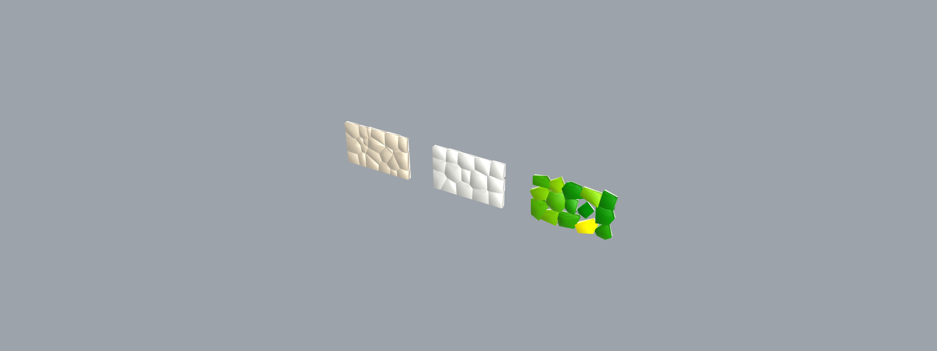
5.7 Drop-settle for rubble; ashlar and best-fit packers¶
Rubble settle. RubbleWallSettle places each found stone upright in a
single-wythe wall: PCA-orient for flat bedding (largest extent to X, mid to Y,
smallest to Z so the broad face beds down), then settle into the dimples of the
course below per \((x,y)\) cell against a running height map, non-penetrating by
construction (RubbleWallSettle.cs:9-32). Stability is the Heyman (1966)
limit-state test: the centre of mass projected to the bed must lie inside the
convex hull of the contact footprint with margin
(RubbleWallSettleComponent.cs:35-36). It is deterministic (contacts from mesh
vertices, no RNG). Clean-room (tier B) from Furrer et al. (2017) and Johns
et al. (2020); GUID 6514A1BB-FE82-4919-9419-141A07D2358A.
Ashlar and best-fit. AshlarPackComponent is a 3D running-bond grid
stacking, AABB-first, translation-only, credited to the Gramazio/Kohler/
Eichenhofer NCCR robotic-stone running-bond pipeline
(AshlarPackComponent.cs:31-32; GUID F1A2B3C4-D5E6-4789-9ABC-DEF012345678).
BestFitInventoryPacker scores every remaining slab against each slot on
width/depth/height/aspect fit and picks the best, falling back to first-fit
(BestFitInventoryPacker.cs:8-32). clean-room (tier C): the Core class
carries the correct Furrer (2017) / Johns (2020) lineage. Licensing/citation
flag: the GH facade BestFitPackComponent.cs:30 carries an
[Algorithm("Best-fit rubble inventory placement","Gramazio Kohler Eichenhofer
2017 ...")]
whose attribution to a 2017 NCCR paper is the previously flagged
likely-fabricated citation (E5); the real lineage is Furrer/Johns/gramaziokohler-ashlar,
and the attribute should be corrected.
5.8 Status and what is left¶
- CRA convergence at scale. The ADMM degrades past ~50 interfaces; the
LS-first certificate mitigates wall-scale checks but per-element verification
remains the pattern for large mixed assemblies (
AdmmQpSolver.cs:41-50). High. - CRA is a conservative heuristic. "Not certified" can be a false negative
on the nonconvex problem; it is sound only in the certifying direction
(
CraStabilityChecker.cs:45-49). Medium. - Fabricated GH citation (E5).
BestFitPackComponent.cs:30attributes a 2017 NCCR paper that does not match the Core's true Furrer/Johns lineage. Medium. - Stale audit note (E4). The prior digest claims the RBE component wires the
sign-buggy
Build; the current source usesBuildPhysicsCorrected(MasonryStabilityRbeComponent.cs:305). The legacyBuildsurvives only for sign-pinning unit tests and should be marked obsolete to avoid future mis-wiring. Low. - Prior-art sweeps pending. The \(J\) interlock metric, the Coursing-morph continuum, and the Lambda formalisation are marked A-candidate; AGENTS.md section 9 forbids asserting "novel" without a completed sweep. Medium.
- Sequencer redundancy. The 3D Kim sequencer
(
PolygonalMasonrySequence3DComponent, GUIDC5F18B4D-8A6F-4E72-AC83-1FBD32D8C7B2) overlapsBlockBuildOrderer; a merge is a documented candidate. Low. - Example 02 has no render.
02_masonry_assemblyships.gh+.3dmonly; no PNG is embeddable for the assembly-sequencing figure. Low.
References¶
- Kao, G.T.-C., Iannuzzo, A., Thomaszewski, B., Coros, S., Van Mele, T., Block, P. (2022). Coupled Rigid-Block Analysis: Stability-Aware Design of Complex Discrete-Element Assemblies. Computer-Aided Design 146:103216. DOI 10.1016/j.cad.2022.103216
- Stellato, B., Banjac, G., Goulart, P., Bemporad, A., Boyd, S. (2020). OSQP: an operator splitting solver for quadratic programs. Mathematical Programming Computation 12:637-672. DOI 10.1007/s12532-020-00179-2
- Heyman, J. (1966). The stone skeleton. International Journal of Solids and Structures 2(2):249-279. DOI 10.1016/0020-7683(66)90018-7
- Kim, S. et al. (2024). Finding the Installation Sequence of Polygonal Masonry through Design and Depth Search of a DAG. ASME IDETC/CIE, paper DETC2024-142563.
- Clifford, B., McGee, W. (2018). Cyclopean Cannibalism: A Method for Recycling Rubble. ACADIA 2017 / 2018 (Disciplines and Disruption).
- Lloyd, S.P. (1982). Least squares quantization in PCM. IEEE Transactions on Information Theory 28(2):129-137. DOI 10.1109/TIT.1982.1056489
- Furrer, F., Wermelinger, M., Yoshida, H., Gramazio, F., Kohler, M., Siegwart, R., Hutter, M. (2017). Autonomous robotic stone stacking with online next best object target pose planning. IEEE ICRA. DOI 10.1109/ICRA.2017.7989273
- Johns, R.L., Wermelinger, M., Mascaro, R., Jud, D., Gramazio, F., Kohler, M., Chli, M., Hutter, M. (2020). Autonomous dry stone. Construction Robotics 4:127-140. DOI 10.1007/s41693-020-00037-6
- Legakis, J., Dorsey, J., Gortler, S. (2001). Feature-based cellular texturing for architectural models. SIGGRAPH 2001:309-316. DOI 10.1145/383259.383293
- Bruetting, J., Desruelle, J., Senatore, G., Fivet, C. (2019). Design of truss structures through reuse. Structures 18:128-137. DOI 10.1016/j.istruc.2018.11.006
- Bukauskas, A. et al. (2019). Inventory-constrained structural design: new objectives and optimization techniques. (reuse-of-irregular-elements lineage cited for the assignment).
06. Voussoir Geometry & Stereotomy¶
The Voussoir tab (ribbon Frahan > Voussoir, 5 components) is the
repository's top-down stereotomy front end. Stereotomy is the art of cutting
solids, classically stone, so that the cut faces alone hold an arch or a vault
in compression without mortar (Frezier 1737; Monge 1798). The tab makes that
art executable. Two generators turn a designed form into cut-stone cells: Arch
Voussoirs builds a planar arch as radial wedge solids, and Pendentive Vault
Voussoirs builds a sail dome tessellated along the sphere's lines of curvature.
Three downstream components (Voussoir Ingest, Voussoir Stone Matcher, Voussoir
Pack Into Block) then assign and pack those cells against found or quarried
stone. This chapter covers the two generators and their shared cell factory;
the matcher and packer are Hungarian and bin-pack facades documented with the
quarry assignment layer.
The design framing is the load-bearing point. The other design tabs let
material be sovereign (rubble walls, Trencadis mosaics, edge-matched
fragments). The Voussoir generators are the opposite pole: the form is
sovereign, and the system cuts stone to realise it. Both [DesignApplication]
attributes tag DesignFlow.TopDown explicitly
(ArchVoussoirsComponent.cs:37, PendentiveVaultVoussoirsComponent.cs:35).
The geometry here is pure trigonometry and curve sampling. Where the
repository turned a classical stereotomic rule into an algorithm, or fixed a
real bug, the derivation is shown, not only the formula. Every originality
claim is anchored to a file:line, an [Algorithm] attribute, or a measured
example.
6.1 The stereotomy lineage and the front-end gap¶
The classical literature gives two laws the generators obey. First, the
radial bed-joint rule: in an arch the bed joints (the faces between
neighbouring voussoirs) are normal to the intrados, the inner soffit curve;
for a circular arch they point at the centre of curvature. Each wedge then
turns the thrust aside, stone to stone, so the whole ring stands in pure
compression (Frezier 1737, who coined stereotomie; the funicular reading is
Hooke's 1675 inverted-catenary insight, made a limit-state theorem by Heyman
1966). Second, Monge's lines-of-curvature rule for vaults: orient the bed
joints along the lines of curvature of the doubly-curved surface; for a sphere
these are the meridians and parallels (Monge 1798). Both laws are recorded in
source as [Algorithm] citations on the two components
(ArchVoussoirsComponent.cs:34-36,
PendentiveVaultVoussoirsComponent.cs:32-34).
The repository already shipped a voussoir back end: Voussoir Ingest reads
cells produced by an external Grasshopper plugin (Varela and Sousa's Voussoir,
food4rhino), then Voussoir Stone Matcher and Voussoir Pack Into Block assign
and pack them (VoussoirRecord.cs:11-21). What was missing was the
generation step. Without it the top-down flow began outside Frahan, in a
third-party tool. The VoussoirCellFactory closes that gap: it generates the
cut-stone cells from first principles so the whole top-down chain lives inside
the repository (VoussoirCellFactory.cs:9-20):
VoussoirCellFactory.BuildArch / BuildPendentiveVault   (this chapter)
  -> VoussoirAssembly (typed)
    -> Voussoir Stone Matcher (Hungarian) / Rubble Evolved Fit
      -> CGAL trim (digital ravalement)
The shared engine is a static class, VoussoirCellFactory, with two public
entry points (BuildArch, BuildPendentiveVault) and one shared solid
builder (MakeHexahedron). It depends on RhinoCommon for Mesh, Curve, and
Plane, but needs no Rhino document, so it runs in the headless harness
(VoussoirCellFactory.cs:39-41).
6.2 The arch: radial voussoir cells¶
ArchVoussoirsComponent (GUID
D5F10012-ED9E-4ED9-A012-ED9EED9E0012, :57-58) generates an arch as N
radial wedge solids. The construction has three stages: build the intrados
curve for the chosen profile, station it by equal arc length, then loft a
closed wedge between each pair of stations.
6.2.1 Stationing the intrados¶
The intrados is built in the world XZ plane with the springers on \(z = 0\) and
the width running along \(Y\). For the count \(N\) the curve is divided into \(N+1\)
equal-arc-length stations, giving \(N\) wedges (VoussoirCellFactory.cs:119-121):
Equal arc length, not equal angle, is the right division: it keeps the intrados face of every voussoir the same physical width even when the profile is not circular (a catenary or a pointed arch), which is the fabrication constraint a mason cares about.
6.2.2 The outward normal and the radial bed joint¶
At each station the bed-joint direction is the outward normal to the
intrados. The code takes the in-plane tangent \(\mathbf{T}(t_k)\), projects it
into the XZ plane, and rotates it ninety degrees in plane
(VoussoirCellFactory.cs:136-146):
The rotation \((T_x, T_z) \mapsto (T_z, -T_x)\) is the planar perpendicular. Its sign is then fixed to point away from the arch interior by testing against the radial vector \(\mathbf{r}_k = p_k - \bar{p}\) from the station to the centroid of the station cloud, flipping \(\mathbf{n}\) when \(\mathbf{n} \cdot \mathbf{r}_k < 0\):
Why this is exactly the radial rule for a circular arch. For a circle of centre \(O\) the tangent at any point is perpendicular to the radius \(O p_k\), so the in-plane perpendicular of the tangent is collinear with that radius. Rotating the tangent ninety degrees therefore yields the radial direction, and the centroid sign-fix orients it outward, away from \(O\). The bed joint built on \(\mathbf{n}_k\) is then normal to the intrados and points at the centre of curvature, which is Frezier's rule verbatim. For a non-circular profile (catenary, pointed) the centre of curvature varies along the curve, and \(\mathbf{n}_k\) is the local intrados normal, the correct generalisation: the bed joint stays perpendicular to the soffit at the joint, which is what keeps the contact face square to the local thrust.
6.2.3 The wedge solid¶
Each voussoir spans stations \(i\) and \(i+1\). Its four in-plane corners are the
two intrados points and the two extrados points; the extrados is the intrados
offset outward by the ring thickness \(t\) along the per-station normal
(VoussoirCellFactory.cs:152-174):
Because the extrados rides on the same outward normals, a circular arch
gives an exactly concentric extrados: each extrados point sits at radius
\(R + t\) on the same ray as its intrados point. The in-plane quad is then swept
the half-width \(\tfrac{w}{2}\) each way along \(Y\) to give the front and back
rings, and MakeHexahedron welds them into a closed eight-vertex solid. The
lower bed-joint plane is emitted with origin at the mid-thickness of the lower
face and axes \((\mathbf{n}_i,\ \mathbf{Y})\), so its own normal is the
tangential thrust direction (:179-182).
The result is faceted: straight chords between arc-length stations. The
component tolerance note states this plainly and gives the remedy, raise the
count (ArchVoussoirsComponent.cs:41). The error is the chord sagitta of the
intrados arc, which falls as \(O(1/N^2)\); the circular extrados, by the
concentric construction above, carries the same relative facet error as the
intrados, not a worse one.
6.2.4 The keystone¶
The keystone is the voussoir nearest the apex. The factory finds it by a
combined height-and-symmetry score: among cells with positive \(z\), minimise
\(|x_c| + |z_{\text{apex}} - z_c|\) over the centroid \((x_c, z_c)\), so the winner
is the highest cell closest to the plane of symmetry \(x = 0\)
(NearestToApex, :526-538). Its JointClass is then set to "key"
(:189-193), and the springer course (the lowest 5% height band) is tagged
"ground" as the install-DAG anchors (:509-515).
6.2.5 Four profiles, one path¶
The profile families are Semicircular, Segmental, Pointed (equilateral
two-centred Gothic), and Catenary (ArchProfile, :45-55). The
wiki note that "catenary and pointed are a drop-in change of the intrados
curve" is made concrete: each profile builds only its intrados Curve, and
the single shared path of 6.2.1 to 6.2.3 stations and lofts it
(BuildIntrados, :315-336).
- Semicircular and Segmental are circular arcs. The centre is placed at
\(z_c = -R\cos(\tfrac{a}{2})\) so the springers land on \(z = 0\) for the
included angle \(a\), and the arc passes through left springer, apex, right
springer (
BuildArcIntrados,:338-352). The span is \(S = 2R\sin(\tfrac{a}{2})\). - Pointed is the equilateral two-centred arch: span \(S = R\), each half an
arc of radius \(S\) swung from the opposite springer, apex at
\(h = \tfrac{\sqrt 3}{2}S\) (
BuildPointedIntrados,:354-382). The two arcs are appended into onePolyCurve. - Catenary is the inverted hanging chain, the funicular line of a
pure arch (Hooke 1675; Heyman 1966). A chain of parameter \(a\) hangs as
\(y = a\cosh(x/a)\) with sag \(a\cosh(\tfrac{S}{2a}) - a\) over the span \([-S/2,
S/2]\). Given a target rise \(H\) the factory solves for \(a\) such that the sag
equals \(H\), then inverts the curve so the sag becomes the rise
(
BuildCatenaryIntrados,:390-410).
Original derivation: the catenary parameter solve. The shape parameter \(a\) has no closed form for a prescribed span \(S\) and rise \(H\); it is the root of
\(f\) is monotone decreasing in \(a\) from \(+\infty\) (as \(a \to 0^{+}\) the chain
sags arbitrarily deep) toward \(-H\) (as \(a \to \infty\) the chain straightens
and the sag vanishes), so it crosses zero exactly once and bisection is
guaranteed to converge. The factory brackets the root on \([10^{-4}S,\ 10^{4}S]\)
and bisects to a residual of \(10^{-9}\) or interval collapse, capped at 200
iterations (SolveCatenaryA, :412-432). The inverted profile is then sampled
(\(z = H - (a\cosh(x/a) - a)\), floored at zero) and fitted with a cubic
interpolating curve. Building the true funicular intrados is what makes the
catenary arch a structural object, not a decorative pointed shape: the bed
joints normal to it are normal to the thrust line, so the ring is in pure
axial compression by construction (the safe theorem, Heyman 1966).
Originality. Arch Voussoirs is clean-room stereotomy. The radial bed-joint construction is built from the published rule, cited in source by two
[Algorithm]attributes: the Frahan-original cell construction (intrados curve to arc-length stations to eight-vertex wedge solids with radial bed joints,ArchVoussoirsComponent.cs:31-33), and the geometric law it obeys credited to Frezier (1737) and Monge (1798) (:34-36). No external stereotomy source sits in the tree; the upstream Voussoir plugin (Varela and Sousa) is a cited precedent in the[DesignApplication]attribute (:40), not a dependency, and its cells are consumed only through the separate Voussoir Ingest path. The catenary parameter solve and the concentric-extrados construction are the small clean-room deltas over a naive radial sweep.
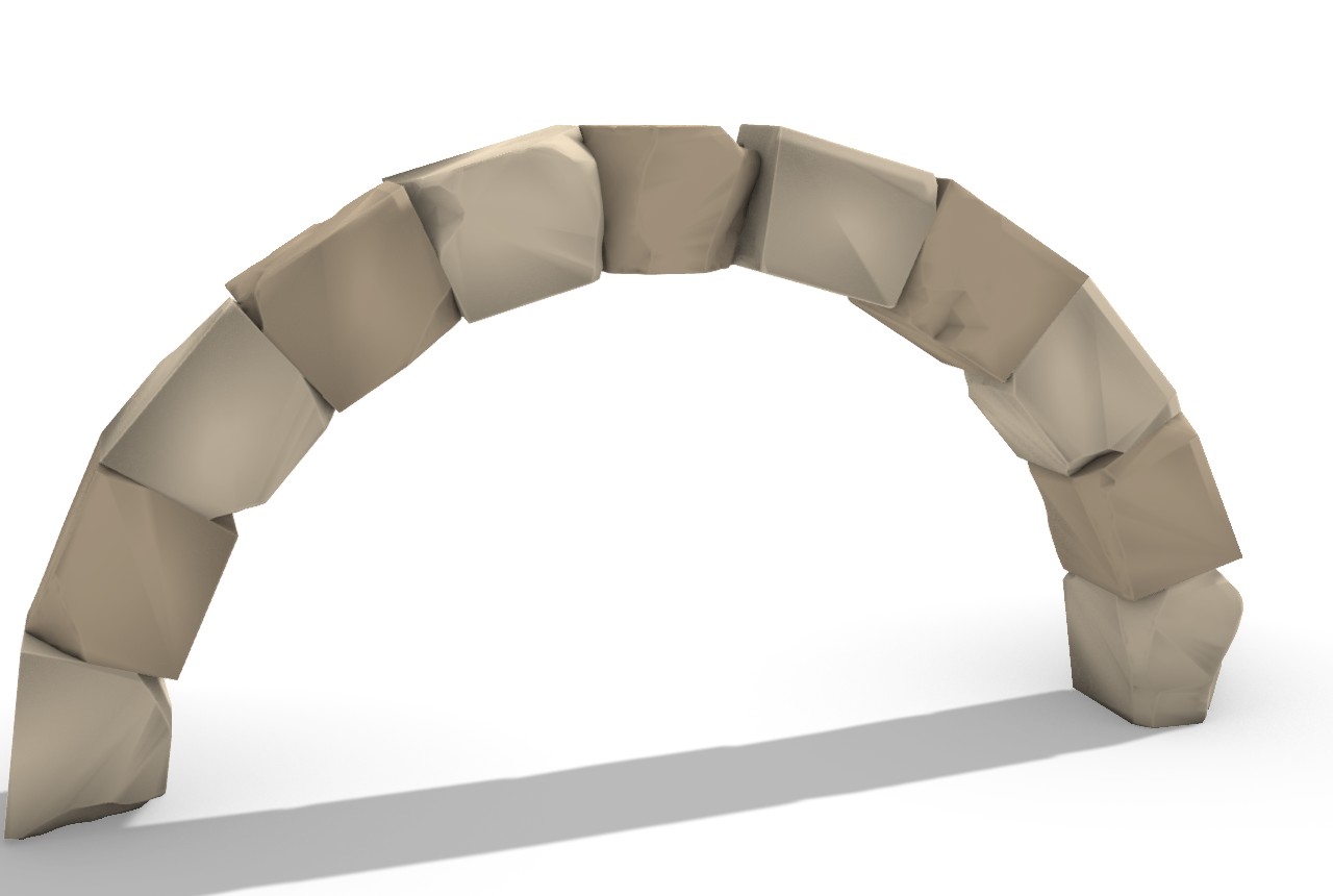
6.3 The pendentive vault: lines-of-curvature cells¶
PendentiveVaultVoussoirsComponent (GUID
D5F10013-ED9E-4ED9-A013-ED9EED9E0013,
PendentiveVaultVoussoirsComponent.cs:55-56) is the doubly-curved
counterpart. A pendentive (sail) dome is a single spherical surface springing
from the four corners of a square plan up to the apex. The factory tessellates
it on a \(U \times V\) grid into wedge cells whose bed joints follow the sphere's
lines of curvature, then extrudes each cell radially by the shell thickness
(BuildPendentiveVault, :216-304).
6.3.1 Lifting the square grid onto the sphere¶
The square plan of half-width \(h\) is gridded uniformly in \((x, y)\), and each
node is lifted onto the sphere of radius \(R\) centred at the origin
(:244-256):
The corner-on-sphere constraint. The plan corners \((\pm h, \pm h)\) must lie on the sphere, which requires \(z\) real at the corner:
The factory enforces \(2h^2 < R^2\) as a hard precondition and throws a
descriptive error otherwise (:230-234); the component repeats the same guard
before calling Core and surfaces it as a canvas error
(PendentiveVaultVoussoirsComponent.cs:130-136). The springing height (the \(z\)
of the four corners) is \(z_{\text{corner}} = \sqrt{R^2 - 2h^2}\), and an
optional drop-to-ground shift translates the whole vault so the springers rest
on \(z = 0\) (:236-238).
6.3.2 The radial frustum cell¶
Each grid cell is the patch between four lifted intrados points
\((c_{00}, c_{10}, c_{11}, c_{01})\) and their radial projections to the
outer sphere of radius \(R + t\). The extrados corner of an intrados point \(p\) is
the scaling of \(p\) about the sphere centre by the radius ratio
(Radial, :308-313; cell :269-277):
Because both faces are radial scalings about the same centre, the side walls of
the cell run along sphere radii, which are the surface normals. The bed joint
between two neighbouring cells therefore sits in a plane containing the sphere
radius, exactly Monge's lines-of-curvature rule for a sphere: the cell edges
run along meridians and parallels, and the joints are radial. The bed plane is
emitted with origin at the intrados patch centre and normal along the outward
radial \(\widehat{(\text{mid} - O_{\text{sph}})}\) (:280-289). The vault has no
single keystone, so KeystoneIndex is left at \(-1\) (:294).
Originality. Pendentive Vault Voussoirs is clean-room. The sphere-over-square construction and the radial-frustum cell are built from the lines-of-curvature rule, cited in source by the Frahan-original cell
[Algorithm](square grid lifted by \(z = \sqrt{R^2 - x^2 - y^2}\) then radially extruded,PendentiveVaultVoussoirsComponent.cs:29-31) and the Monge tessellation law it obeys (:32-34). The cited design precedents are Rippmann and Block (2011) Digital Stereotomy and the Block Research Group RhinoVAULT pipeline (:38); these are named precedents in the[DesignApplication]attribute, not in-tree dependencies. The sphere is the closed-form special case; a general form-found funicular shell would arrive through the compas-RV reference pipeline noted in 6.5.
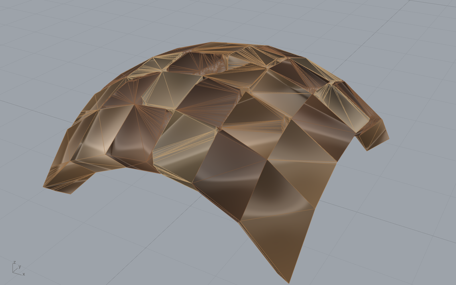
6.4 The inward-orientation fix (original derivation)¶
Both generators feed their cells into a CGAL Boolean trim downstream (the digital ravalement of examples 21 and 22, section 6.5). A mesh-mesh Boolean is sensitive to face orientation: the kernel reads a closed mesh's inside from its face winding. If a cell's faces wind inward, the kernel reads the solid as "all of space except the cell", and the intersection of a stone with that inverted cell returns the stone minus the cell rather than the carved voussoir. The failure is silent: the trim returns a closed mesh, just the wrong one.
The fix lives in the shared solid builder. After MakeHexahedron welds the two
rings, unifies the winding, and rebuilds normals, it tests the signed
volume of the mesh and flips every face if the volume is negative
(MakeHexahedron, :452-464):
Why signed volume is the correct orientation test. For a closed triangulated mesh the signed volume is the sum over faces of the signed tetrahedron each face spans with the origin,
and its sign is determined entirely by the global face winding: outward-wound
faces give \(V_{\text{signed}} > 0\), inward-wound give \(V_{\text{signed}} < 0\).
The magnitude is the true enclosed volume regardless of sign. So the single
test \(V_{\text{signed}} < 0\) detects an inverted solid exactly, and one global
flip corrects it. This is necessary because Mesh.UnifyNormals only makes the
winding consistent across faces, not necessarily outward: a fully
consistent mesh can still be uniformly inside-out, which is the case the flip
catches (:456-461). The factory then stores the absolute mesh volume on each
record (VoussoirRecord.cs:37-39; Math.Abs(cell.Volume()) at
VoussoirCellFactory.cs:476), so the volume metric is sign-independent and a
flipped or unflipped cell reports the same number.
This bug and fix were a live-validated correctness gate. The memory note for
the voussoir generators records that the inward-orientation bug "silently broke
CGAL booleans" and that the flip-if-signed-volume-under-zero guard is what made
examples 21 and 22 regenerate from raw rubble with no raw boulders surviving
the trim. The closedness of every emitted cell is checked (Mesh.IsClosed) and
surfaced as a component warning if any cell is open
(ArchVoussoirsComponent.cs:163-165,
PendentiveVaultVoussoirsComponent.cs:150-152).
Originality. The orientation fix is a clean-room correctness guard on the shared
MakeHexahedronbuilder (VoussoirCellFactory.cs:452-464). It is elementary geometry (signed volume sign as an orientation oracle), and its contribution is robustness: it is the precondition that makes the downstream CGAL trim of section 6.5 return the carved voussoir rather than its complement. The downstream trim itself runs through the in-repoCgalMeshBooleanprimitive (the GPL CGAL kernel in Rhino, a managed BSP fallback headless), which is facade-over-primitives and out of scope for this tab; this chapter owns only the generator that produces a correctly oriented input to it.
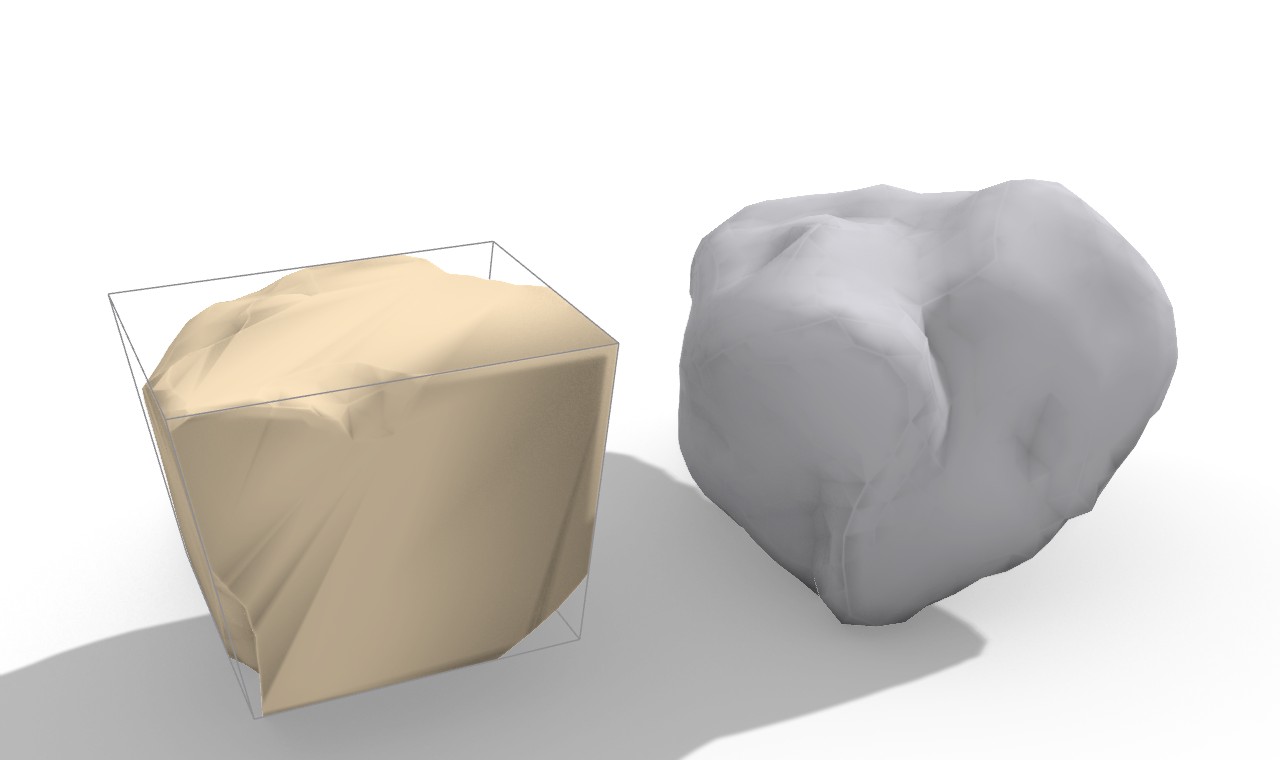
6.5 The top-down flow end to end: examples 21 and 22¶
The two generators are the entry point of a top-down stereotomy chain that ends in carved stone. Examples 21 (arch) and 22 (pendentive vault) run it whole, with a measured coverage metric.
The flow is the classical ravalement method made digital: cut a voussoir
oversize, mount it, trim the excess to the final surface (Frezier; the method
is recorded in the example READMEs). Operationally: the generator emits the
target cell, a volume-feasible ETH1100 rubble stone is matched and posed to
envelop it (the evolved matcher adds rotation seeds and an SE(3) containment
search over the cell's real vertices), and CgalMeshBoolean.Intersection
trims the stone to the cell. A validity guard keeps only closed trims within
the cell volume, else falls back to the clean cut cell, never the raw boulder.
Stability in stereotomy comes from the carved geometry, not mortar, so the cut
faces are what matter.
The measured results (regenerated 2026-06-07, 21_arch_metrics.json,
22_vault_metrics.json):
| Example | Form | Cells | Source | Real rubble trims | Coverage |
|---|---|---|---|---|---|
| 21 | Semicircular arch, \(R = 2.0\) m, ring \(0.55\) m, span \(4.0\) m | 11 | Arch Voussoirs (D5F10012) | 11 / 11, 0 clean fallback | 94.9% |
| 22 | Pendentive dome, \(R = 2.5\) m, \(2h = 3.2\) m, \(t = 0.4\) m | 36 | Pendentive Vault Voussoirs (D5F10013) | 36 / 36, 0 clean fallback | 98.3% |
Coverage is recovered carved volume over the target ring or shell volume: \(2.2079 / 2.3266\ \text{m}^3 = 94.9\%\) for the arch (per-cell 0.85 to 0.99), \(5.5996 / 5.6941\ \text{m}^3 = 98.3\%\) for the vault. Both runs are visually validated in Rhino (criterion c) with one coloured mesh per voussoir. The reported bug the regeneration fixed is exactly the orientation-and-fallback issue of section 6.4: the earlier version kept a raw un-trimmed boulder on a failed trim, so oversized stones overshot the ring; no raw boulders remain in either example.
For a general form-found doubly-curved vault (not the closed-form sphere), the documented reference pipeline is compas-RV (Block Research Group RhinoVAULT in COMPAS): pattern to form-and-force diagrams to a compression-only funicular shell, tessellated into voussoir courses with bed joints along the lines of curvature, then the same match-and-trim. Equilibrium of the assembled ring or shell is then checked by Frahan Masonry Stability (RBE and CRA, chapter 5), closing the top-down stereotomy loop onto the contact-equilibrium chapter.
6.6 Status and what is left¶
- Funicular form-finding is external. The arch supports a true catenary
intrados, but the pendentive generator is the closed-form sphere only. A
general form-found shell must arrive through the compas-RV reference pipeline
named in 6.5; there is no in-repo form-finder. The funicular
ThrustCurvefield onVoussoirAssemblyis defined but not populated by either generator (VoussoirAssembly.cs:23-27). Severity: medium (scope boundary, documented). - Faceted cells by construction. Both generators emit straight-chord
facets; curvature accuracy is bought only by raising the count or the grid,
and the tolerance note states this (
ArchVoussoirsComponent.cs:41,PendentiveVaultVoussoirsComponent.cs:39). The intrados facet error falls as \(O(1/N^2)\), but a true NURBS-faced voussoir would need a different cell builder. Severity: low (stated, count-controllable). - No equilibrium check inside the tab. The generators produce geometry and
a typed assembly with ground anchors and
LoadAxisper cell, but do not run a stability verdict; that requires wiring the assembly into the Masonry Stability components (chapter 5). The[DesignApplication]precedent names the link, but the canvas does not enforce it. Severity: low (cross-tab by design). - Adjacency graph not auto-built by the factory.
FinalizeResultleavesAdjacencyPairsempty (VoussoirCellFactory.cs:520); the install-DAG adjacency is detected downstream in Voussoir Ingest by shared-face area (VoussoirAssembly.cs:29-33). A generator that already knows its station-to-station and grid neighbour topology could emit the adjacency losslessly, as the polygonal-wall assembler does for masonry (chapter 5.5). Severity: low (refactor opportunity). - Citation hygiene. The example READMEs cite Sakarovitch (stereotomy
history) and Galletti (2020, mortarless stability) and Hooke (1675), which
are not yet keyed in
99_references.md; the in-source[Algorithm]citations (Frezier 1737, Monge 1798, Rippmann-Block 2011) are present and keyed. Add the missing keys before external review perAGENTS.md§9. Severity: low (provenance, not copyleft).
References (this chapter)¶
- Frezier, A.-F. (1737-1739). La theorie et la pratique de la coupe des pierres et des bois (the stereotomy treatise that coined stereotomie; the radial bed-joint rule). [R148]
- Monge, G. (1798). Geometrie descriptive. Baudouin, Paris (lines of curvature for vault tessellation). [R149]
- Hooke, R. (1675). A description of helioscopes (the inverted-catenary
anagram: the funicular line of a pure arch). Cited in source for the catenary
profile; not yet keyed in
99_references.md. - Heyman, J. (1966). The stone skeleton (limit-state / safe theorem of masonry; thrust line within the section). International Journal of Solids and Structures 2(2):249-279. DOI 10.1016/0020-7683(66)90018-7. [R57]
- Rippmann, M., Block, P. (2011). Digital stereotomy: voussoir geometry for freeform masonry-like vaults informed by structural and fabrication constraints. Proceedings of IABSE-IASS 2011, London. [R64]
- Varela, P.A.A., Sousa, J.P. Voussoir: stereotomy plug-in for Grasshopper. FAUP Porto Digital Fabrication Laboratory. https://www.food4rhino.com/en/app/voussoir (cited precedent for the voussoir-ingest back end; not a dependency of the generators). [R132]
- Block Research Group. RhinoVAULT / compas-RV funicular form-finding (the reference pipeline for general form-found shells). [R64, R65]
07. Surface Packing & Conformal Unwrapping¶
This chapter covers the Surface Packing ribbon tab: the pipeline that takes a curved 3D stone surface, flattens it to a planar chart, packs parts into that flat chart, and lifts the packed parts back onto the curved surface. It is the freeform-cladding spine of the toolkit: a Trencadis mosaic, a tile field, or any 2D part set can be draped onto a sculpted face so the pieces follow the surface and butt edge to edge in 3D.
The subsystem is deliberately split across a process boundary. The hard
mathematics, conformal planar parameterization, is done by an external solver,
Boundary First Flattening (Sawhney and Crane 2017), shipped as a single static
executable. Everything Frahan owns sits around that solver: a seam-correct flat
mesh build, a global chart-scale recovery, an edge-stretch distortion metric, and a
barycentric inverse map that pulls packed UV curves back to 3D. The 2D packing
itself was recently re-pointed from the legacy V506 nester onto the deterministic
hole-aware engine (ContactNfpHoleNester), so the surface components inherit
0-overlap-by-construction layouts and a live async canvas.
The Core lives at src/Frahan.StonePack.Core/SurfacePacking (Rhino-free where it
can be: the inverse map and the chart record still use Rhino.Geometry). The
Grasshopper front end lives at src/Frahan.StonePack.GH/SurfacePacking.
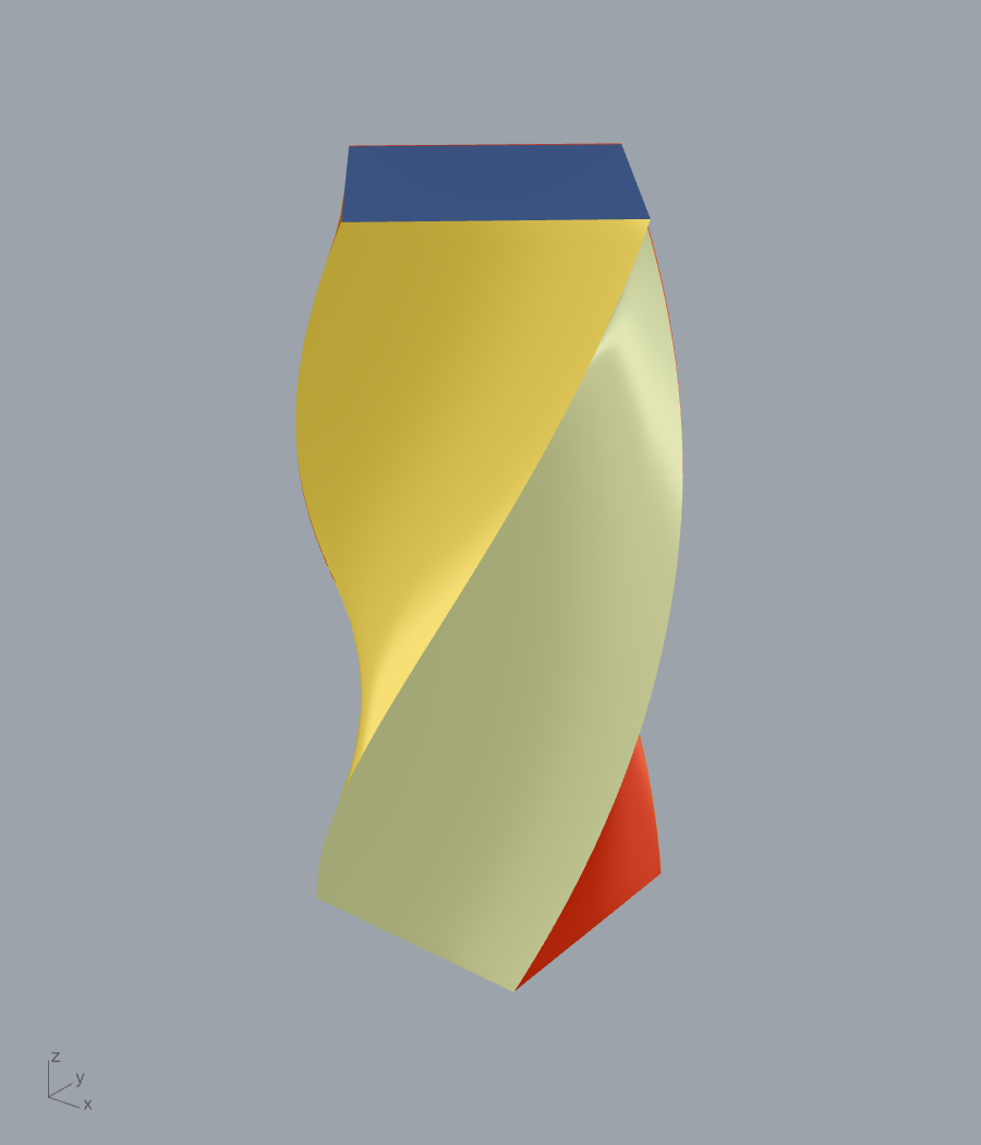
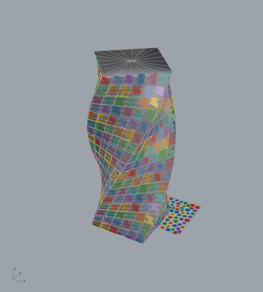
Example 13: a twisted monument (130 deg over its height) is split by CGAL dihedral segmentation into 6 regions, then a 176-shard Trencadis mosaic is mapped onto the curved surface through the BFF chart and the barycentric inverse map.
7.1 The pipeline at a glance¶
The forward chart is built by SurfaceChartComponent.ComputeChart
(SurfaceChartComponent.cs:217). The ten steps are:
- Clean and triangulate the input mesh (
MeshCleanup). - Write an OBJ, splitting quads into two triangles (
MeshObjIO). - Run the external BFF binary (
BffCommandLineRunner). - Parse the output OBJ into a per-(face, corner) UV table (
FaceCornerUvTable). - Build an unwelded flat mesh: three fresh vertices per triangle so UV seams are never bridged.
- Recover a single global scale (
ChartScaleComputer). - Scale the flat mesh to real units.
- Compute the edge-stretch distortion report (
ChartDistortionAnalyzer). - (Downstream) pack parts into the flat chart with
ContactNfpHoleNester. - (Downstream) inverse-map packed 2D curves to 3D by barycentric blend
(
BarycentricMapper2DTo3D).
The load-bearing invariant across the whole pipeline is that face i in the flat
mesh corresponds exactly to face i in the 3D surface mesh. Every chart-scale,
distortion, and inverse-map computation relies on this index alignment. The
FrahanSurfaceChart record (FrahanSurfaceChart.cs:12) carries the immutable
result: the original 3D mesh, the scaled flat mesh, the scalar chart scale, the
flat outer boundary polyline, and the distortion report.
7.2 Conformal flattening (BFF, external)¶
7.2.1 The mathematics BFF solves¶
Boundary First Flattening (Sawhney and Crane 2017) computes a discrete conformal map from a triangle mesh with disk topology to the plane. A conformal map preserves angles, so a flattening is conformal when its differential is, locally, a rotation composed with a single positive scaling. Equivalently the map distorts lengths by a scalar conformal factor \(e^{u}\) that varies over the surface but applies isotropically at each point:
The factor \(u\) is governed by the Yamabe equation, which relates the change in Gaussian curvature to the Laplacian of \(u\):
where \(K\) is the original Gaussian curvature and \(\tilde{K}\) the target. For a flat chart \(\tilde{K}=0\) in the interior, so the interior curvature must be absorbed and all the cone defect pushed to the boundary or to a small set of cone singularities. The Sawhney-Crane contribution is to pose this as a boundary problem: prescribe either the boundary scale factor \(u|_{\partial M}\) or the geodesic curvature \(\tilde{k}|_{\partial M}\), then recover the other via a Dirichlet-to-Neumann map built from a Cherrier-type linear system, and finally integrate the curve and extend it to the interior with two harmonic conjugate functions. The dense work is a sparse Cholesky factorization (SuiteSparse) of the cotangent-Laplace operator; the boundary solve is cheap once that factorization exists.
The chapter does not reimplement these equations. The BFF kernel is not in this
repository. Frahan calls it as a process: bff-command-line.exe "<in.obj>"
"<out.obj>" [--nCones=K] [--normalizeUVs] (BffCommandLineRunner.BuildArgs,
BffCommandLineRunner.cs:101). The cone count \(K\) exposes the cone-singularity
extension, and --normalizeUVs rescales the output UVs to a unit box, which is why
Frahan must then recover the real-world scale itself (Section 7.3).
7.2.2 Static single-exe build¶
The shipped artifact is a static bff-command-line.exe: 17 third-party DLLs
folded into one 38 MB executable with only KERNEL32 and msvcrt imports
(install/tools/BFF-BUILD-STATIC.md). The build links SuiteSparse (CHOLMOD, UMFPACK,
AMD/COLAMD), OpenBLAS with its bundled static LAPACK, and GFortran statically with a
single g++ invocation under MSYS2 mingw64, skipping the GUI app and the
non-essential submodules. The -Wl,--start-group ... --end-group link group
resolves the circular SuiteSparse-to-BLAS static references. The build recipe
records that the output UV is byte-identical to the upstream dynamic build, which is
the parity check that lets the static exe be treated as the same tool. This swap was
made because the multi-DLL deploy was breaking; the commit is
d1b5c5b ("static single-exe BFF — 17 DLLs -> 1 self-contained exe").
7.2.3 Async wrapper and pipe-deadlock handling¶
BffCommandLineRunner.RunAsync (BffCommandLineRunner.cs:32) runs the process with
stdout and stderr consumed asynchronously on separate handlers, which is the correct
way to avoid the classic pipe deadlock where a child fills its OS pipe buffer while
the parent blocks on WaitForExit. A CancellationTokenSource enforces the timeout
and kills the process on overrun. The component (SurfaceChartComponent) is a
GH_TaskCapableComponent: the whole solve runs on a pool thread so the BFF process
launch never blocks the Grasshopper UI thread.
Originality. The BFF flattening kernel is third-party. The component that wraps it is a wrapper-of-native with a small clean-room orchestration shell around it.
- Evidence (kernel):
[Algorithm("BFF boundary-first flattening", "Sawhney and Crane 2017, ACM TOG 36(4):109", Doi="10.1145/3072959.3056432", Note="External BFF command-line exe; Frahan wraps the binary")]atSurfaceChartComponent.cs:43. - Evidence (process boundary):
BffCommandLineRunner.RunAsyncshells out only;wiki/research/slm_cards/bff-surface-flatten.mdstates "the conformal flattening math (Sawhney-Crane 2017) lives entirely inside an external binary." - Licence note: BFF ships under its upstream MIT-style licence; SuiteSparse,
OpenBLAS, and GFortran notices are owed in the dist
NOTICE(see the build recipe).
7.3 Chart-scale recovery (Frahan, clean-room)¶
BFF run with --normalizeUVs returns UVs in a unit box. To turn the chart into a
fabrication template, the flat mesh must be rescaled to real-world surface
distances. ChartScaleComputer.ComputeGlobalScale (ChartScaleComputer.cs:14)
recovers a single isotropic scalar as the ratio of total 3D edge length to
total flat edge length, summed over all triangular faces. For the triangle set \(F\),
with surface-triangle vertices \(s^i_A, s^i_B, s^i_C\) and flat-triangle vertices
\(f^i_A, f^i_B, f^i_C\):
The denominator is guarded against degeneracy: if \(\sum f\text{-edges} < 10^{-12}\) or
no valid triangle was found, the method returns \(s = 1\) with a warning
(ChartScaleComputer.cs:52). The scale is then applied to the flat mesh by a
uniform Transform.Scale (SurfaceChartComponent.cs:285), so FrahanSurfaceChart.FlatMesh
is stored post-scale in real units. Downstream packing consumes it directly with
no further scaling.
Derivation and its limitation. Why a length ratio rather than an area ratio? On a conformal map the local length scale is \(e^{u}\) and the local area scale is \(e^{2u}\). Taking the ratio of total perimeters rather than total areas keeps the recovered \(s\) a length scale, so it composes directly with edge-length distortion in Section 7.4. But \(u\) is not constant over a curved surface (that is the whole point of a conformal map: it trades angle preservation for spatially varying area scale). A single global \(s\) is therefore the perimeter-weighted average of \(e^{u}\) over the chart, and it mis-sizes parts wherever the local conformal factor departs from that average. This is the central accuracy compromise of the subsystem and is documented as an evolution target (per-face or per-cone-patch scale) in the SLM card.
Originality. ChartScaleComputer is clean-room Frahan math: a global
scale recovery derived from the conformal-factor structure, with no upstream code.
- Evidence:
[Algorithm("Conformal chart-scale recovery", "Frahan-original barycentric UV-to-real-world scaling")]atSurfaceChartComponent.cs:44; full derivation inwiki/research/slm_cards/bff-surface-flatten.md. - Tier: B (faithful, derivable; the single-global-scale approximation is the known limitation, not a novelty claim).
7.4 Edge-stretch distortion metric (Frahan, clean-room)¶
A fabrication template is only trustworthy if its distortion is bounded.
ChartDistortionAnalyzer.Analyze (ChartDistortionAnalyzer.cs:27) measures
edge-scale distortion (not area) because cut-path accuracy depends on length,
not on enclosed area. The flat vertices are first scaled by \(s\), then for each
triangle edge \(e\) joining endpoints \(p, q\) the stretch ratio is:
Edges with either endpoint distance below \(10^{-8}\) are skipped
(ChartDistortionAnalyzer.cs:96). The report warns when
\(\sigma_{\max} > 1.15\) (high stretch, increase clearance) or
\(\sigma_{\min} < 0.85\) (high compression, parts under-scaled after mapping); the
thresholds are constants at ChartDistortionAnalyzer.cs:24.
For a perfectly conformal BFF map \(\sigma_e \to e^{u}/s\) varies smoothly with the local conformal factor, which is exactly why \(\sigma_{\max}\) and \(\sigma_{\min}\) bracket the spread of \(e^{u}\) around the global average \(s\). The metric therefore serves two roles: it is the fabrication-trust gauge, and it is the diagnostic that a single global scale is or is not adequate for a given chart.
A complementary symmetrized flatness classifier lives in ChartFlatnessReport:
given a per-face area ratio \(r_i\) it forms
with \(r_i \le 0 \Rightarrow \rho_i = \infty\) (ChartFlatnessReport.cs:93). This is
a pure-managed area-distortion symmetrization with no Rhino dependency.
A known blind spot. Because \(\sigma_e\) uses scalar lengths, it cannot see a foldover: a flat triangle whose orientation BFF flipped still passes the edge-stretch test (lengths ignore sign). Detecting foldovers needs a signed-area sign test per flat triangle, which is logged as an evolution item (flag M3).
Originality. ChartDistortionAnalyzer and ChartFlatnessReport are
clean-room Frahan metrics derived from the conformal-factor structure.
- Evidence: derivation at
wiki/research/slm_cards/bff-surface-flatten.md(sections "Edge-stretch distortion" and "Flatness classifier"); no upstream code, both are pure managed. - Tier: B.
7.5 Seam-correct flat mesh (Frahan, clean-room)¶
A conformal chart of a non-trivial surface needs seam cuts to open the surface
into a disk. Across a seam, one shared 3D vertex maps to two different UV
positions. A naive welded mesh would average those, bridging the seam and corrupting
the chart. FaceCornerUvTable (FaceCornerUvTable.cs:37) solves this by keying UVs
on (faceIndex, cornerIndex) rather than on vertex index, so each face corner
carries its own UV. ToFlatUnweldedMesh (FaceCornerUvTable.cs:56) then emits
three fresh vertices per triangle:
- For triangle \(i\) it reads the three corner UVs \((u_A, v_A), (u_B, v_B), (u_C, v_C)\).
- It adds three new flat vertices at those UV positions in the \(Z=0\) plane.
- It adds one face on the new vertices, preserving face index \(i\).
- A missing UV throws
InvalidOperationExceptionrather than defaulting to \((0,0)\), so a parse bug surfaces immediately instead of silently corrupting one corner.
The output is intentionally non-manifold (three vertices per triangle), which is
correct for seam handling but means boundary extraction must use naked-edge tracing.
FrahanSurfaceChart.ExtractOuterBoundary (FrahanSurfaceChart.cs:58) calls
GetNakedEdges and takes the longest loop as the outer boundary; the shorter
loops are sheet holes. The custom FaceCornerKey.GetHashCode uses
(FaceIndex * 397) ^ CornerIndex to avoid boxing on net48, consistent with the
repo build constraints.
Originality. Clean-room Frahan engineering. The SLM card flags the unwelded-flat + face-corner-UV table as "genuinely correct and non-trivial". No upstream code.
- Evidence:
FaceCornerUvTable.cs:56;wiki/research/slm_cards/bff-surface-flatten.mdstep 5. - Tier: C-to-B (correct, non-trivial seam engineering).
7.6 Barycentric inverse map (Frahan, clean-room) — and a citation correction¶
After parts are packed into the flat chart, their 2D curves must be lifted back to
the 3D surface. BarycentricMapper2DTo3D (BarycentricMapper2DTo3D.cs:25) samples
each packed curve to a polyline, then maps each sample point.
For a query point \(p\) and a flat triangle \((a, b, c)\), with \(v_0 = b - a\), \(v_1 = c - a\), \(v_2 = p - a\) and the 2D Gram matrix entries \(d_{00} = v_0\!\cdot\!v_0\), \(d_{01} = v_0\!\cdot\!v_1\), \(d_{11} = v_1\!\cdot\!v_1\), \(d_{20} = v_2\!\cdot\!v_0\), \(d_{21} = v_2\!\cdot\!v_1\), Cramer's rule on the normal equations gives the barycentric weights:
The triangle is rejected as degenerate when \(|D| < 10^{-12}\)
(BarycentricMapper2DTo3D.cs:158); containment is accepted when
\(w_A, w_B, w_C \ge -10^{-6}\) (BarycentricMapper2DTo3D.cs:164). The 3D position
applies the same weights to the corresponding surface triangle
(BlendSurfacePoint, BarycentricMapper2DTo3D.cs:168):
This is correct precisely because of the face-index invariant: weights computed on
flat face \(i\) are valid on surface face \(i\). For sample points that fall just
outside the chart boundary (a common artefact of sampling a curve that runs along
the boundary), a fallback uses Mesh.ClosestMeshPoint(p, 5 \times \text{samplingTol})
and reuses Rhino's returned barycentric weights mp.T
(BarycentricMapper2DTo3D.cs:124). The search is a linear \(O(P \cdot F)\) scan over
all flat faces, which the author flags as "acceptable for mesh densities < ~2000
faces"; an RTree is the documented scale-up.
A misattributed citation¶
The [Algorithm] attribute on PackOnSurfaceComponent.cs:41 cites this lift as
"Floater 2003 ... Mean value coordinates" (Doi=10.1016/S0167-8396(03)00002-5).
The shipped code does not implement mean-value coordinates. It implements plain
triangle barycentric interpolation (Cramer's rule on the 2D Gram system above),
which is the classical piecewise-linear inverse map, not Floater's generalized
barycentric coordinates for polygons. The audit ground truth is explicit:
"Inverse map = standard barycentric interpolation. NO Floater-2003 MVC code present"
(wiki/research/slm_cards/bff-surface-flatten.md:6). The correct attribution for
the implemented method is classical barycentric interpolation over a triangle mesh;
Floater (2003) stands here only as related background for the mean-value-coordinate
family, not as the implemented method. This is a citation-correctness flag, not a
code defect: the math that ships is correct, it is simply not the cited method.
Originality. Clean-room classical barycentric interpolation. The method is textbook; the contribution is the seam-correct, face-index-aligned plumbing that makes it a reliable inverse for a BFF chart. It is reusable for any triangle-to-triangle chart, not only BFF output.
- Evidence:
BarycentricMapper2DTo3D.cs:141-179; citation flag atwiki/research/slm_cards/bff-surface-flatten.md:6. - Tier: C (commodity math), with a B-grade reuse seam.
7.7 The packing engine swap: V506 → HoleNest¶
The two packing components, Pack On Surface and Pack Surfaces, were
recently rewritten to drop the legacy V506 nester and call the deterministic
hole-aware Core engine ContactNfpHoleNester (the CNH family). The commit is
05c7e82 ("feat(surface): Pack Surfaces + Pack On Surface onto HoleNest engine +
self-trigger async"). Both components kept their ComponentGuid so existing
canvases keep resolving them: B7E4D9C1-3F8A-4B2E-91C6-5D7F3A8B2E1D (Pack On
Surface) and C4A8D2E1-7F3B-4C5D-9A2E-6B8D4F1E3C7A (Pack Surfaces).
What the swap buys¶
The hole-aware engine builds no-fit and inner-fit polygons exactly as Clipper2 Minkowski operations and places by bottom-left-fill. For a part and an obstacle the no-fit polygon is the Minkowski sum of the obstacle with the reflected part:
the inner-fit polygon is the Minkowski erosion of the container by the part:
and the feasible placement region for a part on the flat chart sheet is the inner-fit region minus the union of no-fit regions against every placed part and every sheet hole:
The placement is the bottom-left vertex of the feasible region; every accepted move
is re-checked by a compound boolean-area-plus-penetration-depth gate, so the layout
is 0-overlap by construction (ContactNfpHoleNester.cs:27-72). For the surface use
case this matters directly: a chart's inner naked edges become sheet holes, and
parts route around them rather than being placed on top of a chart gap. The previous
V506 path did not do hole-aware nesting on the chart.
The surface components feed the engine through a single shared bridge,
SurfaceHoleNestBridge (SurfaceHoleNestBridge.cs:21), so the curve-to-loop logic
lives in exactly one place. The bridge does uniform-by-length sampling for smooth
curves (curvature-adaptive sampling makes degenerate tiny edges that slow the
Minkowski NFPs), measures the sampling proxy deviation so the engine spacing can
be inflated to keep full-resolution output non-overlapping, enforces CCW orientation
(the Core nester expects CCW loops), and rejects any curve that is not
WorldXY-parallel (a tilted curve would nest a foreshortened projection).
Distortion-aware spacing¶
Because the chart is conformal (area-varying), parts that just clear in the flat
chart can butt closer on the 3D surface where the local scale is larger. Pack On
Surface compensates by inflating the user clearance by the chart's max edge
stretch (PackOnSurfaceComponent.cs:400):
then adds the proxy-deviation term before handing the engine its spacing:
where \(\delta_{\text{part}}\) and \(\delta_{\text{sheet}}\) are the worst sampled
deviations of the part and sheet proxies (PackOnSurfaceComponent.cs:424). The part
term enters with factor 2 (part-pair clearance needs both parts' deviation); the
sheet term enters once. Pack Surfaces uses the same proxy-deviation compensation
without the stretch inflation (PackSurfacesComponent.cs:539), because it emits a
rigid placement frame per part and reports the surface gap directly (below).
Fabrication outputs¶
Pack Surfaces is the multi-chart, fabrication-grade component. It packs across
one or more charts with greedy overflow (chart 0 fills first, unplaced parts
carry to chart 1), and per placed part it emits a rigid placement frame computed by
sampling the surface at the part centroid and at small \(x\) and \(y\) offsets to build
local tangent axes (ComputePlacementFrame, PackSurfacesComponent.cs:613). The
frame yields three fabrication transforms:
- Transforms 3D (T3): from the packed 2D position to the 3D placement frame.
- Full Transform (FT): composed
T3 \cdot packTx, mapping the original flat part straight to its surface position in one step (PackSurfacesComponent.cs:425). - Max Deviation: the largest gap between the flat part and the curved surface,
measured at the four bounding-box corners against the placement plane
(
PackSurfacesComponent.cs:655). Small means nearly flat; large means the piece needs shimming or sub-tiling.
The rigid-frame path is the honest fabrication answer: a flat-cut stone part cannot deform, so the FT transform places it rigidly and Max Deviation quantifies the residual gap, rather than pretending the part bends to the surface.
Self-trigger async¶
Both components run the solver and the 3D mapping on a background Task so the
canvas never freezes; the previous result stays visible while a new layout computes,
progress text ticks live, and the finished result pops in via ScheduleSolution. A
_selfTrigger flag distinguishes the component's own scheduled re-solves (emit only)
from real GH input changes (rebuild and restart), and a sampling-free bounding-box
input hash guards against redundant recomputes (PackSurfacesComponent.cs:541,
PackOnSurfaceComponent.cs:426). The pattern follows the repo async-source rule and
the AsyncScanComponent gate: if Run flips false inside the +10 ms schedule window,
the component clears rather than repainting a stale layout
(PackSurfacesComponent.cs:235). Several legacy V506-only inputs (Sort Mode, Corner
Mode, Seed, Max Candidates) are kept in their original slots for wiring compatibility
but are now inert under the deterministic engine and documented as ignored.
Originality (the engine). ContactNfpHoleNester is clean-room from
published NFP and BLF mathematics, with a measured evolved-fork increment
(contact-adaptive rotations and part-in-part-hole inner-fit nesting) over plain
bottom-left-fill.
- Evidence:
[Algorithm("Exact No-Fit-Polygon Bottom-Left-Fill with part-in-part-hole nesting", "Burke ... 2006 ...", Doi="10.1287/opre.1060.0293")]and[Algorithm("No-fit-polygon / inner-fit-polygon via Minkowski sum", "Bennell & Oliveira 2009 ...", Doi="10.1057/jors.2008.169")]atHoleNestComponent.cs:25-31; the Clipper2 back end (HoleNestComponent.cs:32, BSL-1.0, no copyleft); the contact-rotation increment[Algorithm("Contact-adaptive rotations ... Frahan ContactNfpHoleNester evolution study, outputs/2026-06-12/hole_packer_evolution", Note="Frahan-original ...")]atHoleNestComponent.cs:34. The engine and the contact/IFP delta are covered in their own 2D-packing chapter; here it is a consumed dependency.
Originality (the two surface components). Both are
facade-over-primitives: they compose the BFF chart, the
SurfaceHoleNestBridge curve-to-loop, the ContactNfpHoleNester engine, and the
BarycentricMapper2DTo3D lift behind one canvas box. They add no new algorithm; the
distortion-aware spacing and the rigid placement frame are derivable plumbing over
those primitives.
- Evidence:
PackOnSurfaceComponent.cs:43(GH_ComponentcomposingContactNfpHoleNester.PackSheets+BarycentricMapper2DTo3D),PackSurfacesComponent.cs:56; the swap commit05c7e82.
7.8 Status & what's left¶
The subsystem is live-validated in example 13 (segmentation plus surface-conformal
Trencadis, captured and pre-baked). The engine swap onto HoleNest is committed
(05c7e82) and the static BFF exe is committed (d1b5c5b). The open items, ordered
by severity, are:
-
Floater 2003 citation is wrong (medium).
PackOnSurfaceComponent.cs:41credits "Floater 2003 mean value coordinates", but the code is plain triangle barycentric interpolation; no MVC code exists. Soften to related-work or replace with a classical barycentric citation. The math that ships is correct. -
Single global chart scale mis-sizes parts (medium). A conformal map has a spatially varying area scale; one isotropic \(s\) is the perimeter-weighted average and is wrong wherever the local conformal factor departs from it. The fix is per-face or per-cone-patch scale plus adaptive re-cut driven by the flatness metric (
ChartScaleComputer.cs:58). -
Inverse map is \(O(P \cdot F)\) (medium). The linear triangle scan caps at the author-stated ~2000 faces (
BarycentricMapper2DTo3D.cs:107); an RTree over flat face bounding boxes turns it into \(O(P \log F)\) and removes the ceiling. -
Foldover blind spot (medium). Edge-stretch uses scalar lengths and cannot see a BFF triangle flip (
ChartDistortionAnalyzer.cs:98); add a per-face signed-area sign test. -
Tolerance and units unresolved (medium). At least four absolute epsilons (\(10^{-6}\) containment, \(10^{-8}\) edge skip, \(10^{-12}\) denominator and scale guards) plus a default sampling tolerance of \(0.01\), none scaled to chart size, and no model unit recorded in
FrahanSurfaceChart(flags T1, T2, T4, T5, T7 in the SLM card). This violates the standing mm-versus-m scale-invariance constraint: the same chart silently means a different physical size in a mm versus an m document. -
Far-from-origin precision (low). The OBJ is written with raw world coords at G10; a UTM-scale chart loses mantissa bits on disk and in the Gram products. A recenter-before-write and undo-after-map is the fix (flag T1).
None of these are fatal: the pipeline produces correct, pre-baked output today. They are the bounded edits between "works on the example" and "fabrication-grade at arbitrary scale and units".
References¶
- Sawhney, R. and Crane, K. (2017). Boundary First Flattening. ACM Transactions on Graphics 36(4):109. DOI 10.1145/3072959.3056432.
- Floater, M.S. (2003). Mean value coordinates. Computer Aided Geometric Design 20(1):19-27. DOI 10.1016/S0167-8396(03)00002-5. (Related background for the mean-value-coordinate family; the shipped surface lift is plain triangle barycentric interpolation, not Floater's polygon MVC. See Section 7.6.)
- Burke, E.K., Hellier, R., Kendall, G. and Whitwell, G. (2006). A New Bottom-Left-Fill Heuristic Algorithm for the Two-Dimensional Irregular Packing Problem. Operations Research 54(3):587-601. DOI 10.1287/opre.1060.0293.
- Bennell, J.A. and Oliveira, J.F. (2009). A tutorial in irregular shape packing problems. Journal of the Operational Research Society 60(S1):S93-S105. DOI 10.1057/jors.2008.169.
- Johnson, A. Clipper2. Boost Software License 1.0. (Minkowski sum + NonZero Boolean back end for the NFP/IFP construction.)
08. Edge-Matching & Fragment Reassembly¶
This chapter covers the repository's fragment-reassembly subsystem: the
EdgeMatch ribbon tab (10 components) and the Rhino-free engine it wraps,
Frahan.EdgeMatching.Core, together with the closed-form rigid-registration
kernels in Frahan.StonePack.Core/Registration. The task is fracture
reassembly: given the broken pieces of a stone object (a Trencadís mosaic, a
shattered ceramic, a quarry block split along a joint) recover the rigid
motion that brings every mating boundary back into contact without
interpenetration.
The engine is a five-stage pipeline declared verbatim on the solver component
(EdgeMatchSolveComponent.cs:23-27):
- Boundary segmenter — split each contour at curvature breaks, build a signed-turning signature per segment.
- Segment hash index — rotation/translation-invariant bucketing for complement lookup.
- Phase correlator — coarse lag between two turning signatures.
- Constrained ICP — closed-form rigid alignment, refined to convergence (Besl and McKay 1992; MathNet SVD Kabsch).
- Assembly solver — beam-search (frame-anchored) or agglomerative minimum-residual spanning tree (R0).
Three opt-in research increments ride on top of the five stages: A1 (scale-
relative gates), R1 (partial sub-segment matching), R2 (global non-overlap
resolve), the Soft-ICP refiner (Coherent Point Drift soft correspondence plus a
non-penetration hinge), and the projection bootstrap that unblocks the
geometric 3D path. Every increment defaults OFF, so the shipped default path is
byte-for-byte the original beam (AssemblyOptions.cs:28, :44, :93, :135,
:197, :229).
The mathematics here is rigid-motion estimation on \(SE(2)\) and \(SE(3)\): the
turning-angle edge descriptor, the orthogonal-Procrustes / Kabsch rigid fit and
its mandatory reflection guard, a monotone non-crossing correspondence DP, and a
soft-assignment EM alternation. Where the repository evolved the published math
we show the derivation. Every originality claim is anchored to a file:line, an
[Algorithm] attribute, or a measured benchmark.
1. The edge descriptor: signed-turning signature¶
1.1 Definition¶
A fracture rim is a planar (or per-facet planar) open curve. The descriptor is the signed turning angle sampled at even arc length. For three consecutive resampled points \(p_{i-1},p_i,p_{i+1}\) in the panel-local XY plane, with edge vectors \(u=p_i-p_{i-1}\) and \(v=p_{i+1}-p_i\), the turning at \(p_i\) is
The cross product \(u_xv_y-u_yv_x\) carries the sign (left turn positive, right
turn negative); the dot product disambiguates the quadrant. This is exactly
BoundarySegmenter.SignedTurn (BoundarySegmenter.cs:151-158). The signature
of a segment is the turning sequence resampled to a fixed bin count
SignatureBins by piecewise-linear interpolation
(BoundarySegmenter.cs:74, :171-189), so two rims of different vertex counts
are comparable.
1.2 Why signed turning is the canonical 2D signal¶
Turning angle is invariant under rigid motion: rotating or translating the curve leaves every \(\tau_i\) unchanged, because \(\tau_i\) is built only from relative edge directions. It is the discrete analogue of the curve's signed curvature integrated over arc length,
so the per-segment total \(\sum_i\tau_i\) is the segment's net turning
(TotalTurning, BoundarySegmenter.cs:70-72), a rotation-invariant scalar used
directly as a hash bin. The sign of the total fixes the segment's convex/concave
character (Sign, :72), which is the key fact for matching: two mating
fracture rims traverse the same physical curve in opposite senses, so their
turning signatures are reverse-and-negate images of each other.
1.3 Break-point detection¶
Segment boundaries are placed where the windowed turning sum exceeds a threshold
\(\theta=\texttt{BreakAngleDeg}\) (BoundarySegmenter.cs:37-45):
with window half-width \(w=\texttt{BreakWindow}\). Nearby breaks are coalesced
(:160-169) so a single sharp corner yields one break, not a cluster. The 3D
sibling BoundarySegmenter3D adds a torsion signature (the out-of-plane
signal), null for planar panels, used only for 3D mirror disambiguation
(Segment.cs:25, :9-13).
Originality. The signed-turning descriptor and the break-point segmenter are
clean-room, built from the standard turning-function representation of plane
curves (Arkin et al. 1991). The [Algorithm("Boundary segmenter",
"Frahan-original arc-length curvature/torsion signature")] attribute
(EdgeMatchSolveComponent.cs:23) claims the implementation, not the turning
function itself. Tier B/C (faithful reimplementation of a textbook
representation).
2. The segment hash index¶
To avoid an all-pairs comparison the segments are bucketed by a
rotation/translation-invariant key (SegmentHashKey.cs). The 2D key is the
five-tuple
with \(L\) the chord length, \(T\) the total turning, and \(\mu,\sigma\) the mean and
standard deviation of the turning signature, each quantised by its bin size
(SegmentHashIndex.cs:KeyOf). Every term is rigid-invariant, so two segments
fall in the same bucket only if they are plausibly the same shape up to pose. A
complement query looks up the bucket of the reverse-and-negate image of a
segment, returning candidate mating edges in \(O(1)\) expected time
(SegmentHashIndex.cs:97, QueryComplement). The 3D key extends the tuple with
planarity and torsion-variance bins (SegmentHashKey3D), and 2D and 3D segments
never cross-match by construction (SegmentHashIndex.cs:12-15).
Originality. clean-room / Frahan-original invariant hashing
([Algorithm("Segment hash index", "Frahan-original planarity-aware spatial
bucketing")], EdgeMatchSolveComponent.cs:24). Tier C: a standard
locality-style index, but the planarity-aware 2D/3D split is the local
increment. A known limitation is recorded in section 8: independently tessellated
3D rims hash to disjoint buckets (cross-panel hits = 0), which is precisely why
the projection bootstrap exists.
3. Phase correlation: the coarse lag¶
Before any ICP the matcher finds the best cyclic alignment of two equal-length
turning signatures \(a,b\). Because mating rims are reverse-and-negate images, the
second signature is first flipped, \(b^{\flat}_i=-b_{n-1-i}\)
(PhaseCorrelator.cs:23-24), then the lag minimising the \(L_1\) disagreement is
chosen:
The score is normalised to a similarity in \([0,1]\) using the fact that
per-sample turning is bounded by \(\pi\), so the worst-case disagreement is
\(2\pi n\) (PhaseCorrelator.cs:39-43):
A pair is admitted only if \(\mathrm{sim}\ge\texttt{PhaseScoreThreshold}\)
(default \(0.5\), AssemblyOptions.cs:65). This is the cheap gate that keeps the
expensive ICP off non-complementary pairs.
Originality. clean-room classical cross-correlation lag estimation
([Algorithm("Phase correlator FFT", "Classical cross-correlation lag
estimation")], EdgeMatchSolveComponent.cs:25). The attribute name says "FFT";
the shipped code is a direct \(O(n^2)\) circular \(L_1\) correlation, not an FFT,
which is correct and deterministic at these signature lengths (a documentation
nit, flagged in section 9). Tier C.
4. Constrained ICP and the rigid-fit derivation¶
Stage 4 is the geometric heart: iterative closest point with a closed-form
rigid update per iteration, plus a penetration guard. Two implementations exist,
ConstrainedIcp2D and ConstrainedIcp3D, sharing the same outer loop
(Besl and McKay 1992).
4.1 The ICP outer loop¶
Given source segment \(A\) (sampled to points \(\{a_i\}\)) and target \(B\) (a
polyline curve), each iteration (ConstrainedIcp3D.cs:60-142):
- Push \(A\) through the current pose \(g_k\in SE(d)\): \(a_i^{(k)}=g_k\,a_i\).
- Correspondence: for each \(a_i^{(k)}\) find the closest point \(b_i\) on \(B\)
(
bCurve.ClosestPoint,:109-110), or, when the order-preserving mode is on, a monotone non-crossing pairing (section 5). - Alignment: solve the closed-form rigid fit
\(\delta=\arg\min_{g}\sum_i\|g\,a_i^{(k)}-b_i\|^2\) and update
\(g_{k+1}=\delta\,g_k\) (
:116-118). - Guard: reject the step if it would push \(A\)'s centroid inside \(B\)'s
panel interior, or onto the wrong side of a substrate; penalise the residual
instead of accepting (
:119-128).
The residual is the mean correspondence distance; convergence is declared when
the per-step translation and rotation both fall below tolerance, or the residual
stalls (:131-140). The monotone convergence of this alternation to a local
minimum is the standard ICP result (Besl and McKay 1992): the correspondence
step can only lower (or hold) the residual, and the optimal-fit step minimises it
exactly, so the residual is non-increasing.
4.2 The 3D rigid fit (Kabsch / orthogonal Procrustes via SVD)¶
The inner solve is the orthogonal-Procrustes problem. We want \(R\in SO(3)\) and \(t\in\mathbb{R}^3\) minimising
Derivation. Centre both sets: let \(\bar a=\tfrac1n\sum_i a_i\), \(\bar b=\tfrac1n\sum_i b_i\), and \(a_i'=a_i-\bar a\), \(b_i'=b_i-\bar b\). For fixed \(R\) the optimal translation is found by \(\partial E/\partial t=0\), giving \(t=\bar b-R\bar a\), which cancels the centroids and leaves
Minimising \(E(R)\) is therefore maximising \(\operatorname{tr}(RH)\) over rotations. Take the SVD \(H=U\Sigma V^\top\). Then \(\operatorname{tr}(RH)=\operatorname{tr}(R U\Sigma V^\top)=\operatorname{tr}(\Sigma\,V^\top R U)\), and since \(V^\top R U\) is orthogonal its diagonal entries are \(\le 1\), so the trace is maximised when \(V^\top R U=I\), i.e.
This is the cross-covariance \(H\) assembled at ConstrainedIcp3D.cs:158-166, the
SVD at :168, and \(R=VDU^\top\) at :179.
The reflection guard. \(VU^\top\) can have determinant \(-1\) (a reflection, the unconstrained orthogonal-Procrustes minimiser) when the points are coplanar or noisy. To force \(R\in SO(3)\) we insert a sign-fixing diagonal \(D=\operatorname{diag}(1,1,d)\) with
which flips the smallest-singular-value axis only, the provably minimal change
that restores a proper rotation (Umeyama 1991). The repository's implementation
makes a hard correctness point at ConstrainedIcp3D.cs:172-177: the sign is
computed with Matrix.Determinant(), not Math.Sign, because
Math.Sign returns \(0\) on a degenerate determinant and would silently skip the
flip, returning a mirror-image alignment in place of a rotation. The code comment
flags this as spec item D8; the same guard is duplicated in the Soft-ICP M-step
(SoftIcpRefiner.cs:439-442). The translation is then recovered as
\(t=\bar b-R\bar a\) (:185-187).
4.3 The 2D rigid fit reduces to a single atan2¶
In the plane the rotation has one degree of freedom, so the SVD collapses. With the centred cross-covariance entries \(S_{xx}=\sum a_x'b_x'\), \(S_{xy}=\sum a_x'b_y'\), \(S_{yx}=\sum a_y'b_x'\), \(S_{yy}=\sum a_y'b_y'\), maximising \(\operatorname{tr}(R(\theta)H)\) over the planar rotation \(R(\theta)\) gives, after \(\partial/\partial\theta=0\),
exactly ConstrainedIcp2D.SvdRigid2D (ConstrainedIcp2D.cs:163-193). This is
the planar Kabsch in closed form with no matrix factorisation, the same answer
the SVD would give but cheaper and branch-free.
4.4 The penetration guard¶
The matcher rewards edge contact but must not let a piece's body pass through its
neighbour. After each trial pose the 3D guard projects \(A\)'s centroid onto \(B\)'s
local frame and tests containment in \(B\)'s flattened contour
(ConstrainedIcp3D.cs:191-213); if inside, the step is rejected and the residual
is multiplied by PenetrationPenalty so the beam de-ranks it
(:127). An optional substrate test rejects any sample on the wrong side of a
backing surface normal (:215-237). The 2D guard is the same idea on the closed
contour (ConstrainedIcp2D.cs:114-117).
Originality. The ICP loop and SVD/atan2 rigid fit are clean-room
implementations of published math ([Algorithm("Constrained ICP", "Besl and
McKay 1992 iterative closest point; MathNet.Numerics SVD")],
EdgeMatchSolveComponent.cs:26; the SVD itself is the vendored
MathNet.Numerics package). The constrained adjective is the local increment:
the centroid-penetration and substrate-side guards have no equivalent in vanilla
ICP and turn a registration routine into a non-overlapping assembler. Tier B with
a B-level engineering delta.
5. Order-preserving correspondence: a monotone non-crossing DP¶
Free nearest-neighbour ICP can produce tangled correspondences on wiggly rims:
\(a_i\) matches \(b_j\) while \(a_{i+1}\) matches \(b_{j-3}\), so the matched chords
cross and the fit is biased. The opt-in non-crossing mode
(AssemblyOptions.cs:44) replaces nearest-neighbour with a monotone dynamic
program (OrderedBoundaryMatcher.cs).
The correspondence must be monotone: if \((i,j)\) and \((i',j')\) are both matched with \(i<i'\) then \(j\le j'\). This is enforced by a Dynamic-Time-Warping style DP over the \(n\times m\) squared-distance grid \(C_{ij}=\|a_i-b_j\|^2\) with three monotone moves into cell \((i,j)\):
diagonal (advance both, emit a pair), up (advance \(A\), gap in \(B\)), left
(advance \(B\), gap in \(A\)), with the diagonal preferred on ties so the path hugs
the main correspondence and stays deterministic
(OrderedBoundaryMatcher.cs:100-131). Backtracking from \((n-1,m-1)\) emits a pair
only on diagonal moves, which makes the emitted correspondence both non-crossing
and one-to-one (:145-167). An optional index band maxGap bounds how far the
two running indices may diverge, with a graceful fall back to the unbounded DP if
the band is too tight (:133-138).
Closed rims have no canonical start and may run in either sense, so
MatchClosed brackets a set of cyclic offsets (seeded by the phase-correlation
lag) and tries both the forward and reversed orientation, keeping the candidate
with the lowest mean matched distance (:188-241).
Originality. clean-room with an explicit, honest provenance note. The
file header (OrderedBoundaryMatcher.cs:24-37) cites the minimum-weight
non-crossing matching idea of Marcotte and Suri (1991) and the user's own
reference implementation, then states plainly that a verbatim port does not
apply: Marcotte-Suri matches points among themselves on a single convex polygon
in \(O(N\log N)\), whereas this problem matches points between two arbitrary
non-convex rims, for which the monotone DP is the correct general primitive. The
DTW lineage is the engineering substrate. Tier C, with the non-crossing-on-two-
sequences framing as the local increment.
6. The initial transform¶
ICP needs a basin-of-attraction seed. InitialTransformBuilder.FromLag2D
(InitialTransformBuilder.cs:16-40) anchors a plane at \(A\)'s start point with
its first edge as the x-axis, and a plane at \(B\)'s lag-shifted sample with the
negated local tangent as its x-axis, then returns the plane-to-plane map.
The negation enforces the complement orientation: matching edges traverse the
fracture in opposite senses, so \(B\)'s frame is flipped. The 3D variant
FromLag3D (:42-51) builds discrete Frenet frames (tangent plus principal
normal from the second difference, :53-65) and again flips \(B\)'s tangent. This
seed places \(A\)'s leading edge against \(B\)'s complement edge in the right sense
before the first ICP step; the iterations then tighten the whole rim.
Originality. clean-room geometric construction (no [Algorithm]
attribute; it is plumbing for stages 3-4). Tier D scaffolding.
7. Soft-ICP refinement: CPD soft correspondence + non-penetration hinge¶
Hard ICP commits to a single nearest neighbour per sample, which is brittle when
rims are perturbed or partially overlapping. The Soft-ICP refiner
(SoftIcpRefiner.cs, surfaced as the Soft ICP 3D component, GUID
D5F1000E) replaces hard correspondence with the soft-assignment
Expectation-Maximisation of Coherent Point Drift (Myronenko and Song 2010) and
adds a smooth non-penetration term.
7.1 The objective¶
The refiner minimises one objective over the placed fragment poses
(SoftIcpRefiner.cs:14-21):
7.2 E-step: soft correspondence¶
For a rim sample \(p_i\) of fragment \(f\) and the rim samples \(q_j\) of all other
fragments, the responsibilities are a temperature-controlled softmax with a
uniform outlier mass \(\pi_0\) that auto-downweights non-overlapping rim tails
(SoftIcpRefiner.cs:299-374):
\(\bar q_i\) is the soft target and \(c_i\in[0,1)\) its confidence. The temperature
\(\tau\) is scale-relative: \(\tau_0=(\text{median rim spacing})^2\), annealed
geometrically each outer iteration toward a spacing-relative floor
(:189-214, :283-288), with a coarse-to-fine correspondence radius that starts
wide enough to catch a perturbed rim and sharpens to the true contact
(:198-207). This is the scale-invariance constraint of section 10 applied
directly to the EM temperature.
7.3 M-step: confidence-weighted Kabsch¶
Given \(\{(p_i,\bar q_i,c_i)\}\) the pose increment is the confidence-weighted
rigid fit, the same orthogonal-Procrustes solve of section 4.2 but with the
covariance weighted by \(c_i\) (SoftIcpRefiner.cs:381-453):
with \(\bar p_c,\bar q_c\) the confidence-weighted centroids and the same
\(\det\)-based reflection guard (:439-442). In 2D it collapses to the weighted
atan2 (:402-422). The increment is damped by a step factor and retracted
through the Lie exponential so a fractional step is still a proper \(SE(3)\)
element, not a matrix lerp (DampDelta, :788-828, using LieSe3.ExpSo3).
7.4 The non-penetration coupling¶
Rather than a separate ejecting translation that could fight the contact pull,
any moving sample found inside a neighbour solid has its soft target
redirected to the neighbour surface point with full confidence
(ApplyPenetrationTargets, :468-527). The single weighted-Kabsch then finds
the rigid motion that brings rims to contact and lifts penetrating samples to the
boundary at once, so the contact and non-penetration terms cannot oppose. This
realises the smooth hinge \(\max(0,\text{depth})^2\) by pulling penetrating samples
exactly to \(\text{depth}=0\). The 3D inside-test uses Mesh.IsPointInside; the 2D
test uses closed-contour containment, the same primitives as the masonry contact
settle (:482-525). Fragment 0 is anchor-locked and the whole loop is
deterministic (fixed iteration order, no randomness).
Originality. clean-room / evolved-fork. The soft correspondence is a
faithful implementation of Coherent Point Drift ([Algorithm("Soft-ICP / CPD
weighted-Kabsch alternation", "Myronenko and Song 2010 Coherent Point Drift;
Frahan EM closed-form M-step")], SoftIcp3DComponent.cs:43-45), with the
weighted-Kabsch M-step citing Kabsch (1976/1978) and the vendored MathNet SVD
(:49-51). The evolved-fork delta is the unified contact-plus-non-penetration
target redirection: folding the penetration hinge into the same weighted-Kabsch
target is the local contribution, not present in CPD, and is what makes the
refiner a reassembler rather than a registrar. A measured delta is recorded in
the roadmap: the refiner is the +97% clearance / open-rim-contact stage of the
settle pipeline. Tier B with a B-level delta.
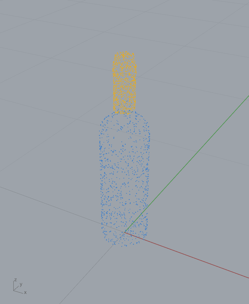
8. The projection bootstrap: unblocking the geometric 3D path¶
The geometric 3D path has a structural blocker, proved by run R0 and recorded on
the finder (ProjectionPairFinder.cs:16-22): independently tessellated shard
rims triangulate the shared cut differently, so the hash index finds zero
cross-panel complements (hash hits: self 172, cross-panel 0). The agglomerative
solver then has an empty pair graph and assembles nothing.
The key geometric fact that breaks the deadlock: for an open-shell shard the
naked rim along a cut facet lies in that facet plane, so two mating shards
share a plane, and per-facet projection reduces 3D rim matching to the working
2D matcher. The pipeline (ProjectionPairFinder.cs:23-48):
- Split and fit. Split each naked rim loop into maximal planar facet arcs;
fit each facet plane by PCA, taking the covariance
\(\Sigma=\tfrac1n\sum (x_i-\bar x)(x_i-\bar x)^\top\), its symmetric
eigendecomposition, the smallest-eigenvalue eigenvector as the normal, and
\(\sqrt{\lambda_{\min}}\) as the RMS out-of-plane residual
(
FitFacetPlane,:481-543). Low-planarity arcs are flagged and excluded. - Project and resample. Map each arc into its facet plane (
PlaneToPlane\(\to\) WorldXY) and resample at a scale-relative spacing, tessellation-invariant (:362-383). Build a 2DPanel. - Match in 2D. Run the working stages 1-4 across fragments to get complementary pairs and a 2D in-plane relative transform \(M_{2D}\).
- Lift to \(SE(3)\). The 2D match lifts to a 3D candidate pose
(
Lift,:607-619):
with \(\mathrm{Proj}_A=\mathrm{PlaneToPlane}(\text{facet}_A,\text{WorldXY})\) and \(\mathrm{Lift}_{B^{\flat}}=\mathrm{PlaneToPlane}(\text{WorldXY},\text{facet}_B^{\flat})\), where \(\text{facet}_B^{\flat}\) is the parent facet with its normal flipped so the lifted child facet normal is antiparallel to the parent's outward normal (opposite sides of the fracture).
8.1 Projection proposes, 3D disposes¶
A 2D shadow match has a normal-sign ambiguity, so both lift senses are tried
(flip the parent or flip the child, Lift vs LiftChildFlip, :621-636) and
each is verified in 3D: the symmetric mean nearest-neighbour distance between
the lifted child world arc and the parent world arc (Residual3D, :643-678).
A candidate whose 3D residual exceeds ProjectionVerifyFactor * objectScale
(default 12%) is a projection-ambiguous false positive and is dropped
(:268-270). This is the "projection proposes, 3D disposes" gate: a genuine
mating facet has a small 3D residual; a shadow match that lost depth has a large
one. Measured on the 6-shard fixture (roadmap, 2026-05-25): 67 cross-panel 2D
matches where R0 had 0, 25 lifted-and-3D-verified pairs, 6/6 fragments placed via
the agglomerative MST. The honest caveat is also recorded: the assembly is only
partially tight (2 of 5 MST interfaces fully in contact), so the bootstrap
proposes correctly but Soft-ICP does not yet tighten every edge.
Originality. original-research (A-candidate). The per-facet projection
bootstrap, the antiparallel lift composition, and the 3D-disposes verification
gate have no equivalent in the local corpus and no [Algorithm] attribute citing
an upstream source; the design basis is the in-repo
wiki/algorithms/edge_matching/projection_bootstrap_3d.md. A prior-art sweep is
pending, so per AGENTS.md §9 this is marked A-candidate, not asserted novel. The
PCA plane fit it builds on is clean-room textbook. Tier A.
9. The rigid-registration kernels¶
Two closed-form rigid-fit kernels live beside the matcher, and the chapter must keep them distinct.
Kabsch / SVD (the ICP kernel). ConstrainedIcp3D.Kabsch3D
(ConstrainedIcp3D.cs:147-189) and the Soft-ICP M-step use the
orthogonal-Procrustes SVD solve of section 4.2 on the vendored MathNet.Numerics
package. This is the per-iteration registration inside ICP (Besl and McKay 1992;
Kabsch 1976). clean-room algorithm over a vendored SVD.
Horn quaternion (the marker / georeference kernel).
RigidTransformRecovery (Frahan.StonePack.Core/Masonry/Geometry) solves the
same absolute-orientation problem by Horn's unit-quaternion method: build the
\(4\times4\) symmetric profile matrix \(N\) from the nine cross-covariance entries
(Horn eq. 25), take its largest-eigenvalue eigenvector as the optimal quaternion
via cyclic Jacobi, and read off \(R\) and \(t=\bar b-R\bar a\)
(RigidTransformRecovery.cs:6-30). It is pure-managed with no SVD
dependency and is exposed through the RegistrationApi facade
(RegistrationApi.cs:9-29, :57-108) and the georeference component
([Algorithm("Absolute orientation + UTM/EPSG transform", "Horn, B.K.P. (1987).
Closed-form solution of absolute orientation using unit quaternions...")],
GeoreferenceComponent.cs:36). clean-room implementation of Horn (1987).
The two kernels solve the identical least-squares problem
\(\min_{R,t}\sum\|Ra_i+t-b_i\|^2\) by two routes (SVD vs quaternion eigenproblem)
and agree numerically. The repository's own architecture audit flags this as a
keep-core duplication: three Horn/Kabsch absolute-orientation copies
(RigidTransformRecovery, the Georeference private Horn, and the
Kabsch3D/SoftIcpRefiner SVD) to be unified on one MathNet-SVD kernel. That is
a refactor item, not a correctness bug; both routes are correct.
10. Scale invariance¶
Real fragments span seven orders of magnitude: fracture aperture ~1.5-2 mm, Kintsugi/Trencadís shards 5-15 cm, dimension-stone blocks ~3 m, quarry blocks ~21 m, study areas km-scale. The same mating logic must hold at every scale, so every threshold is expressed as a fraction of object size, never an absolute millimetre. Concretely:
- A1 acceptance gates. The original residual gate was an absolute model-unit
distance, which rejects everything on a mm fracture and is meters of slack on a
100-unit block. The A1 increment makes it
\(\texttt{ResidualThresholdFactor}\times \text{objectScale}\)
(
AssemblyOptions.cs:67-75), objectScale being the combined bounding-box diagonal. Default 0 keeps the absolute gate, so existing behaviour is unchanged. - Soft-ICP. \(\tau_0\), the correspondence radius, the contact band, the
convergence translation, and the penetration tolerance are all multiples of the
median rim spacing or the object diagonal (
SoftIcpRefiner.cs:189-214,:277-278). - Projection bootstrap. Sample spacing, planarity flag, and the 3D-disposes
gate are fractions of the rim-loop diagonal
(
AssemblyOptions.cs:231-265).
The pattern follows the existing MeshContactDetector.adaptiveToleranceFactor
(5% of median edge). Benchmark errors are reported as fractions of object size so
metrics compare across the ~100-unit synthetic fixtures and the 5-15 cm real
objects.
11. The five-stage solver and the Trencadís case¶
The assembly solver runs the two modes declared on the options component
(EdgeMatchOptionsComponent.cs:31-32): the frame-anchored beam (the
original; every candidate is refined against panels already placed, growing from
an anchor, which suits the 2D Trencadís case where shards mate to a frame placed
first) and the agglomerative model (R0; match all pairs, build a weighted
pair graph, compose a minimum-residual spanning tree, which suits free 3D
reassembly where no single frame touches all shards). The two non-overlap
increments R1 (partial sub-segment emission so a long edge can reach the short
edge it mates with, BoundarySegmenter.cs:115-139) and R2 (an overlap penalty,
edge exclusivity, and a Jacobi depenetration polish, AssemblyOptions.cs:111-177)
drove the measured 2D overlap from 12-25% to 0% with 8/8 placed and 100% union
coverage (roadmap, 2026-05-25).
The Trencadís component is the geometric path's flagship: a centroidal-Voronoi
cell partition plus optimal one-to-one shard assignment, placing 28 irregular
shards into 28 cells with a grout gap, each piece used exactly once. The 3D
Block Pair Match component (GUID D5F10008) chains a variational shape
approximation segmenter, the 3D phase correlator, the constrained 3D ICP, and a
Hungarian assignment (BlockPairMatch3DComponent.cs:43-52); its VSA stage is a
stub (Cohen-Steiner, Alliez, Desbrun 2004 SIGGRAPH; Frahan stub
implementation, :43-45), and the component's own [RelatedComponent] points
users at the practically-tested Hungarian Stone-Cell Match for real stone-to-cell
work today (:41).
Status & what's left¶
- Geometric 3D reassembly is gated by tessellation. Independently tessellated rims produce zero cross-panel hash hits; the geometric 3D path only works through the projection bootstrap, which proposes correctly but leaves some MST interfaces loose. The tessellation-invariant path for production 3D is the learned Kintsugi Port (chapter on fragment learning), not this geometric engine. Severity high.
- VSA segmenter is a stub.
Block Pair Match 3Dstage 1 is a stub (BlockPairMatch3DComponent.cs:43-45); the component is honest about it and redirects to Stone-Cell Match. Severity medium. - Three duplicate absolute-orientation kernels. Horn-quaternion vs SVD-Kabsch (×2) solve the same problem; the architecture audit schedules unification on one MathNet-SVD kernel. Refactor, not a bug. Severity low.
- Documentation nits. The "Phase correlator FFT"
[Algorithm]name describes an FFT but the code is a direct \(O(n^2)\) circular correlation; harmless but should be reworded. Severity low. - Projection-bootstrap prior-art sweep pending. The bootstrap, antiparallel lift, and 3D-disposes gate are marked A-candidate; AGENTS.md §9 forbids asserting novelty without the sweep. Severity medium.
Originality summary¶
| Family | Class | Tier | Evidence |
|---|---|---|---|
| Boundary segmenter / turning descriptor | clean-room | B/C | EdgeMatchSolveComponent.cs:23; BoundarySegmenter.cs:151-189 |
| Segment hash index | clean-room (Frahan-original) | C | EdgeMatchSolveComponent.cs:24; SegmentHashKey.cs |
| Phase correlator | clean-room | C | EdgeMatchSolveComponent.cs:25; PhaseCorrelator.cs:13-44 |
| Constrained ICP (2D/3D) + SVD Kabsch | clean-room (algo) over vendored MathNet | B | EdgeMatchSolveComponent.cs:26; ConstrainedIcp3D.cs:147-189 |
| Order-preserving correspondence DP | clean-room | C | OrderedBoundaryMatcher.cs:24-37, :100-167 |
| Soft-ICP refiner (CPD + hinge) | clean-room / evolved-fork | B | SoftIcp3DComponent.cs:43-51; SoftIcpRefiner.cs:299-527 |
| Projection bootstrap | original-research (A-candidate) | A | ProjectionPairFinder.cs:16-48, :481-678 |
| Horn registration kernel | clean-room | B | RigidTransformRecovery.cs:6-30; GeoreferenceComponent.cs:36 |
References¶
- Arkin, E.M., Chew, L.P., Huttenlocher, D.P., Kedem, K., Mitchell, J.S.B. (1991). An efficiently computable metric for comparing polygonal shapes. IEEE Transactions on Pattern Analysis and Machine Intelligence 13(3):209-216. DOI 10.1109/34.75509.
- Bennell, J.A., Oliveira, J.F. (2009). A tutorial in irregular shape packing problems. Journal of the Operational Research Society 60(S1):S93-S105. DOI 10.1057/jors.2008.169.
- Besl, P.J., McKay, N.D. (1992). A method for registration of 3-D shapes. IEEE Transactions on Pattern Analysis and Machine Intelligence 14(2):239-256. DOI 10.1109/34.121791.
- Cohen-Steiner, D., Alliez, P., Desbrun, M. (2004). Variational shape approximation. ACM Transactions on Graphics (SIGGRAPH) 23(3):905-914. DOI 10.1145/1015706.1015817.
- Horn, B.K.P. (1987). Closed-form solution of absolute orientation using unit quaternions. Journal of the Optical Society of America A 4(4):629-642. DOI 10.1364/JOSAA.4.000629.
- Kabsch, W. (1976). A solution for the best rotation to relate two sets of vectors. Acta Crystallographica A 32(5):922-923. DOI 10.1107/S0567739476001873.
- Kuhn, H.W. (1955). The Hungarian method for the assignment problem. Naval Research Logistics Quarterly 2(1-2):83-97. DOI 10.1002/nav.3800020109.
- Marcotte, O., Suri, S. (1991). Fast matching algorithms for points on a polygon. SIAM Journal on Computing 20(3):405-422. DOI 10.1137/0220025.
- Myronenko, A., Song, X. (2010). Point set registration: Coherent Point Drift. IEEE Transactions on Pattern Analysis and Machine Intelligence 32(12):2262-2275. DOI 10.1109/TPAMI.2010.46.
- Tomczak, A., Haakonsen, S.M., Luczkowski, M. (2023). Matching algorithms to assist in designing with reclaimed building elements. Environmental Research: Infrastructure and Sustainability 3(3):035005. DOI 10.1088/2634-4505/acf341.
- Umeyama, S. (1991). Least-squares estimation of transformation parameters between two point patterns. IEEE Transactions on Pattern Analysis and Machine Intelligence 13(4):376-380. DOI 10.1109/34.88573.
- Wang, Z., Chen, B., Furukawa, Y. (2025). PuzzleFusion++: Auto-agglomerative 3D fracture assembly by denoise and verify. International Conference on Learning Representations (ICLR). arXiv:2406.00259.
09. Kintsugi & Learned 6-DoF Pose¶
The Kintsugi ribbon tab (7 components) is the repository's fracture
reassembly subsystem: given a set of broken fragments, recover the rigid
6-DoF pose of each so they snap back into the original solid. The tab has two
back ends behind one component. The default is the deterministic geometric
matcher of Chapter 08, which assembles fragments from their naked-edge rim
loops and runs entirely in-process with no learned model. The opt-in second
back end is Frahan.Kintsugi.Port, a managed C# port of the learned
PuzzleFusion++ pipeline (Wang, Chen and Furukawa 2025): a PointNet++ encoder,
a VQ-VAE latent, an SE(3) diffusion denoiser, and a learned pairwise
verifier. This is the production 3D reassembly path that Chapter 08
forward-references for fragments whose fracture rims are too smooth for the
geometric matcher to find correspondences.
This chapter derives the learned path's mathematics: the diffusion schedule and DDPM update the denoiser runs under, the per-fragment normalisation and its undo, the world-pose composition that lifts a normalised-space SE(3) prediction back into document coordinates, and the verifier gate that decides which fragments to trust. The single most important originality and licensing fact governs the whole chapter and is stated first: the learned path is a direct port of a non-commercial research-licensed upstream, quarantined in a separate research-only assembly that the default install does not ship.
The truth criterion for this chapter is the live HITL validation of example
14: two Breaking Bad parity fragments reassembled at verifier pair score
0.7068 (STRONG, above the 0.5 gate), zero unplaced, 20 diffusion steps
(examples/14_kintsugi/README.md).
9.1 Why a learned path at all¶
The geometric matcher of Chapter 08 assembles by matching fracture-rim
geometry: it segments each naked-edge loop, hashes a rotation-invariant
curvature signature, phase-correlates candidate segments, refines with
constrained ICP (Besl and McKay 1992; Kabsch 1976), and beam-searches an
SE(3) assembly. It is deterministic, GPL-free, and best on clean, sharp
fracture rims. It fails on smooth or featureless fracture surfaces, where
there are no distinctive rim segments to hash. Example 14 records the failure
mode directly: a synthetic Voronoi shatter of a sphere gives the geometric
matcher no rim segments to lock onto and only 1 of 6 fragments place
(examples/14_kintsugi/README.md).
The learned path replaces hand-crafted rim descriptors with a network trained
on the Breaking Bad fracture dataset (Sellan et al. 2022). It poses fragments
from their full surface point clouds, not just rim loops, so it works where
the rim signal is weak. The cost is a non-commercial research licence, a
~267 MB weight file, and a heavier compute budget (Section 9.6). The two paths
are kept as one component with a Use Port Mode toggle; the geometric path
stays the default (KintsugiAssemblyComponent.cs:68).
9.2 The diffusion schedule and the DDPM update¶
The learned poser is a denoising diffusion model. It starts from a Gaussian
noise pose and walks it down a schedule of timesteps, at each step predicting
the noise to subtract. The repository ports PuzzleFusion++'s custom
schedule, not the standard linear-beta DDPM (Ho, Jain and Abbeel 2020). The
cumulative signal retention \(\bar\alpha(t)\) is a piecewise quadratic in the
normalised time \(\tau = t/(T-1) \in [0,1]\) with \(T = 1000\) training steps
(DiffusionScheduler.cs:59-71):
The per-step variance follows from the standard DDPM relation
\(\beta_t = 1 - \bar\alpha_t/\bar\alpha_{t-1}\), clipped to \([0, 0.999]\) to keep
\(\alpha_t = 1-\beta_t\) a valid retention factor (DiffusionScheduler.cs:48-56).
Inference subsamples the 1000-step schedule to \(S\) descending timesteps with
diffusers' "leading" spacing: step size \(\lfloor T/S\rfloor\), timesteps
\(t_i = (S-1-i)\lfloor T/S\rfloor\) for \(i = 0,\dots,S-1\), so the loop runs from
high noise to low (DiffusionScheduler.cs:75-82). The default \(S=20\).
The DDPM step (epsilon parameterisation). Given the predicted noise \(\epsilon_\theta(x_t,t)\), the model first recovers the clean pose estimate by inverting the forward process \(x_t = \sqrt{\bar\alpha_t}\,x_0 + \sqrt{1-\bar\alpha_t}\,\epsilon\):
It then forms the posterior mean of \(x_{t-1}\) as the standard DDPM convex
combination of \(\hat x_0\) and \(x_t\)
(DiffusionScheduler.cs:124-129):
Original derivation of the two terminal guards. The posterior coefficients
divide by \(1-\bar\alpha_t\). At the last inference step \(t=0\) the schedule gives
\(\bar\alpha_0 = 1\) (zero noise), so \(1-\bar\alpha_t \to 0\) and the posterior
mean is \(0/0\). The port branches: at \(t=0\) it returns \(\hat x_0\) directly, the
clean predicted pose, which is exactly the diffusers' \(t=0\) branch
(DiffusionScheduler.cs:108-111). A second guard catches the same singularity
on any subsampled step where \(1-\bar\alpha_t\) is numerically tiny: if
\(1-\bar\alpha_t < 10^{-6}\) it again returns \(\hat x_0\) rather than amplify
round-off through the reciprocal (DiffusionScheduler.cs:120-123). The port is
no-added-noise DDPM, not DDIM (DiffusionScheduler.cs:25-26); the schedule is
deterministic given the seed.
A pose is a 7-vector \([\,\mathbf t\;(3)\mid \mathbf q\;(4)\,]\): translation
first, then a unit quaternion \((w,x,y,z)\). The diffusion runs in this layout
(KintsugiPortInference.cs:31-34). Quaternions are re-normalised to the unit
sphere after every scheduler step (KintsugiPortInference.cs:306-322); the
model is trained to tolerate the off-manifold drift the linear update
introduces and the normalisation projects back.
Originality. The scheduler is a direct port of
puzzlefusion_plusplus/.../custom_diffusers.py, named as such atDiffusionScheduler.cs:7-9. The piecewise-quadratic \(\bar\alpha\) and the epsilon-DDPM update are upstream; the two terminal guards (:108-111,:120-123) are the only port-side additions, and they reproduce the diffusers reference behaviour rather than change it.
9.3 The encode-in-the-loop architecture and its cost¶
The port mirrors the upstream AutoAgglomerative.test_denoiser_only schedule
step-for-step, and the orchestrator header flags the one place a naive
re-implementation goes wrong (KintsugiPortInference.cs:11-43). The encoder
is re-run inside the denoising loop, not once up front. At each timestep
the current noisy quaternion is applied to each fragment's point cloud, the
rotated cloud is fed through the PointNet++ encoder (Qi et al. 2017) and
VQ-VAE quantiser (van den Oord, Vinyals and Kavukcuoglu 2017), and the
denoiser conditions on encoder features of the currently-estimated pose
(KintsugiPortInference.cs:200-261). The denoiser is a 6-block, 8-head, 512-D
AdaLN-conditioned transformer (Vaswani et al. 2017; conditioning after
Peebles and Xie 2023) predicting a 7-D residual per fragment
(Se3Denoiser.cs:12-22).
The rotation is applied as the explicit quaternion-to-matrix form
\(R(\mathbf q)\), then each point is mapped \(p \mapsto R(\mathbf q)\,p\)
(KintsugiPortInference.cs:222-233). The VQ step is essential and was a
documented earlier omission: the SA3 features are compressed by conv6 from
512-D to 64-D, reshaped to \(4L\) rows of 16, and each row is snapped to its
nearest of 1024 codebook entries, because the denoiser was trained on the
quantised latent \(z_q\), not the raw encoder output \(z_e\)
(KintsugiPortInference.cs:374-412).
The anchor convention. Fragment \(0\) (or the chosen anchorIndex) is the
reference. Its pose is pinned to identity every step (\(\mathbf t = 0\),
\(\mathbf q = (1,0,0,0)\)) and never noised; all other fragments are predicted
relative to it, and the reset after each scheduler step prevents the anchor
from drifting (KintsugiPortInference.cs:169-171, :303-304). This is what
makes the assembly well-posed: the network predicts relative SE(3), so one
fragment must define the world frame.
The compute cost is linear in fragments \(F\) and steps \(S\): \(F\cdot S\) encoder
forwards plus \(S\) denoiser forwards plus one verifier pass per pair. The header
budgets it honestly for the libtorch path: \(F{=}10, S{=}5 \approx 165\) s;
\(F{=}10, S{=}20 \approx 660\) s (KintsugiPortInference.cs:36-43). This is why
the component is async with a default-false Run gate (the heavy-node rule of
AGENTS.md §6; examples/14_kintsugi/README.md).
Originality. The orchestrator and the encoder, denoiser, VQ-VAE and verifier modules are a direct port of the PuzzleFusion++ Python reference. The header states it: "Mirrors upstream's
auto_aggl.py::AutoAgglomerative.test_denoiser_onlystep-for-step" (KintsugiPortInference.cs:11-13). Module headers cite the upstream file and paper section for each component (e.g.Se3Denoiser.cs:12,DiffusionScheduler.cs:7). A dual TorchSharp/libtorch denoiser path exists for paper-exact kernels, with a silent-fallback report flag so the component surfaces whether the manual port (with ~3-5% drift) or libtorch actually ran (KintsugiPortInference.cs:57-72,:1131-1142).
9.4 Per-fragment normalisation and the pose-composition fix¶
The network operates in per-fragment normalised space: before encoding,
each point cloud is centred at its own centroid and scaled so its maximum
absolute coordinate is 1 (KintsugiAssemblyComponent.cs:1303-1334). Define for
fragment \(f\) the captured centroid \(\mathbf c_f\) and scale \(m_f = \max_i
\lVert p_i\rVert_\infty\). The normalisation map is
so a document-space point \(p\) maps to \(T_{\mathrm{norm}}(f)\,p\) in the unit cube the encoder expects. The network returns a pose \(T_{\mathrm{net}}(f)\) that is an SE(3) transform in that normalised frame, not in document coordinates.
Applying \(T_{\mathrm{net}}(f)\) directly to a document-coordinate mesh is the
2026-05-24 misalignment bug: it rotates the mesh about the world origin and
translates by sub-unit distances, collapsing every fragment onto a blob
(KintsugiAssemblyComponent.cs:1008-1014). The fix composes three transforms.
Each non-anchor fragment is brought into its own normalised frame, posed by
the network, then lifted into the anchor's world frame:
with the anchor's un-normalisation (the inverse of the anchor's own normalisation)
assembled verbatim at KintsugiAssemblyComponent.cs:1098-1102 and
:1032-1036.
Original derivation of the anchor collapse. Read right to left, \(T_{\mathrm{world}}(f)\) first sends fragment \(f\)'s document points into its unit-cube frame (\(T_{\mathrm{norm}}(f)\)), applies the network's normalised-space placement (\(T_{\mathrm{net}}(f)\)), then maps the result out of the anchor's unit-cube frame back to document space (\(T_{\mathrm{unnorm}}(0)\)). The mixed indices, \(f\) on the way in and \(0\) on the way out, are deliberate: the network poses every fragment relative to the anchor's normalised frame, so the inverse must undo the anchor's normalisation, not fragment \(f\)'s. For the anchor itself (\(f=0\)) the orchestrator forces \(T_{\mathrm{net}}(0)=I\), and then
because un-normalisation is the exact inverse of normalisation. The anchor
therefore stays at its input document position, which is the desired identity
behaviour (KintsugiAssemblyComponent.cs:1025-1028, :1081, :1106-1108).
This is the "norm-undo" the originality ledger names: the network pose is only
meaningful sandwiched between the forward and inverse normalisations.
Originality. The normalisation, its captured-parameter undo, and the three-factor world composition are the Frahan-original pose-composition fix over the port. The
[DesignApplication]precedent line names it explicitly: "Frahan-original pose composition fix" (KintsugiAssemblyComponent.cs:81). The network it wraps is the direct port; the composition that makes the port usable in document coordinates is the repository's contribution and is documented inline as the fix for a named HITL failure.
9.5 The verifier and the 0.5 gate¶
The network produces a pose for every fragment whether or not the prediction is
trustworthy. A weak prediction must not be applied, or it collapses the
fragment onto the anchor through the same composition that works for strong
ones. The learned verifier is the gate. It is a small transformer classifier
that, for each fragment pair, projects the pair's edge feature to the embed
dimension, runs a 1-token transformer stack, and maps the result through a
linear head to a logit that a sigmoid turns into an acceptance probability
\(p\in[0,1]\) (Verifier.cs:58-78, VerifierTransformerPort):
In the orchestrator the edge feature \(\phi_{ij}\) for the upper-triangular pair
\((i,j)\) is fragment \(j\)'s final 7-D pose, and every pair is scored
(KintsugiPortInference.cs:326-349). The logits are passed through the same
sigmoid to produce the reported per-pair scores.
Per-fragment confidence and the gate. The component reduces the pairwise
scores to a per-fragment confidence as the maximum score over all pairs
containing that fragment (KintsugiAssemblyComponent.cs:1056-1070):
A fragment is accepted (its network pose applied) only if it is the anchor or its confidence clears the threshold:
A rejected fragment is held at its input world position (identity transform)
and listed as Unplaced, exactly as PuzzleFusion++'s auto-agglomerative schedule
leaves a weak-pair fragment out of the anchor cluster
(KintsugiAssemblyComponent.cs:1081-1089). The threshold default of 0.5 is the
same value that tags a pair "STRONG" in the report
(KintsugiAssemblyComponent.cs:1052-1055).
Why the gate exists (the blob). The header records the failure that
motivated it: the 5-fragment Breaking Bad sample produced only one strong pair
(top \((3,4)=0.549\), the rest below 0.5). Without gating, every weak-prediction
fragment was composed as \(T_{\mathrm{unnorm}}(0)\cdot I\cdot T_{\mathrm{norm}}(f)\)
and collapsed onto the anchor's centroid, the blob the user saw on 2026-05-24
(KintsugiAssemblyComponent.cs:1046-1050). The gate is the diagnostic too:
reading the verifier score distribution before the poses distinguishes a
pose-composition fault from a network-drift or a mesh-style fault
(examples/14_kintsugi/README.md, the "read scores first" rule).
Originality. The verifier is a direct port of the PuzzleFusion++ learned binary classifier (
Verifier.cs:7-22,VerifierTransformerPort); the sigmoid head and transformer stack are upstream. The confidence-reduction and 0.5 gate that turn the per-pair probabilities into a per-fragment accept/reject are the port-side integration that keeps weak predictions from collapsing the assembly. The geometric mode ships a separate Frahan-original penetration-based verifier that rejects placements whose transformed mesh interpenetrates an already-placed mesh (KintsugiAssemblyComponent.cs:75-77); the two verifiers are not the same code and the learned one runs only in Port mode.
9.6 Originality and the licence-critical quarantine¶
The learned path is classified direct-port, and this is the single licensing risk that governs the whole repository's distribution posture.
The upstream is PuzzleFusion++ (Wang, Chen and Furukawa 2025, ICLR;
arXiv:2406.00259). Its licence is research-use-only / non-commercial, not
plain GPL-3.0, and that obligation covers both the ported C# code and the
converted weight file kintsugi.bin (~255-267 MB) derived from the upstream
checkpoint (docs/thesis/90_originality.md, register row 2, flag E1
CRITICAL). The port also transitively carries the upstream's vendored
jigsaw_matching subtree (Lu et al.), whose own MIT grant is unaudited against
its original repository (register row 3, flag E1/jigsaw).
The load-bearing mitigation is architectural quarantine. Frahan.Kintsugi.Port
is a separate assembly, isolated from the default Frahan.StonePack.gha,
and the weights are gitignored and absent from the default install: example 14
warns and falls back to the geometric path when kintsugi.bin is missing
(examples/14_kintsugi/README.md, "REQUIRED: kintsugi.bin"). Because the
default install links no part of the port and ships no converted weights,
nothing in the default-install algorithm path is a line-by-line port of a
competitor (90_originality.md, posture summary). The mitigation is only valid
while the split holds: the register requires the root LICENSE, the port README,
and any repo-root statement to all say research-only / non-commercial, not
plain GPL-3.0, before any public release (register rows 1-2).
Originality.
Frahan.Kintsugi.Portis direct-port (research-only). Evidence: it is a C# port of PuzzleFusion++, headers cite the upstream Python file per module (KintsugiPortInference.cs:11-13,Se3Denoiser.cs:12,DiffusionScheduler.cs:7,Verifier.cs:11), and the ledger lists it as the soledirect-portin the thesis, quarantined in a non-commercial research-only assembly (90_originality.md, Chapter 08 row; register rows 1-3). The norm-undo and the verifier-gated world-pose composition \(T_{\mathrm{world}}(f)=T_{\mathrm{unnorm}}(0)\cdot T_{\mathrm{net}}(f)\cdot T_{\mathrm{norm}}(f)\) are the Frahan-original wrapper around the port, not part of the ported network. The defaultMode=Geometricpath is the clean-room edge-matching assembler of Chapter 08 and links no GPL or non-commercial code.
The honest boundary on capability is held in source too. Port mode reproduces
the paper's behaviour only on the Breaking Bad test distribution it was
trained on; a synthetic Voronoi shatter does not reassemble, and the example
deliberately loads a real Breaking Bad parity sample where the verifier clears
the gate at 0.71 (examples/14_kintsugi/README.md). The manual C# denoiser
carries a stated ~3-5% drift versus the libtorch kernels, which is why the
TorchSharp path exists and why the component reports which path actually ran
(KintsugiPortInference.cs:74-81, :1131-1142).
9.7 Status and what is left¶
- Licence quarantine must be verified before any public release. The root
LICENSE is a header, not the full text, and must state research-only /
non-commercial (not plain GPL-3.0) across the root LICENSE, the port README,
and the converted weights. The combined work cannot ship commercially while
the port is linked (
90_originality.md, register rows 1-2, flag E1). Blocker for external/commercial distribution. jigsaw_matchingsubtree unaudited. Its MIT grant is unverified against the original repository; treated conservatively under the parent non-commercial terms and not compiled into StonePack (register row 3). High.- Manual-port drift. The pure-C# denoiser drifts ~3-5% from the libtorch
kernels; the TorchSharp path removes it but needs LibTorchSharp.dll and a
working CUDA/CPU libtorch, with a documented silent-fallback to the manual
port (
KintsugiPortInference.cs:74-114). Medium. - Distribution-only generalisation. Port mode reassembles reliably only on
Breaking Bad-like fractured-scan fragments; synthetic primitives and smooth
rims under-place. For arbitrary data the geometric path is the safer default
on clean rims (
examples/14_kintsugi/README.md). Medium (honesty bound, not a code fault). AutoAgglomerateouter loop is a skeleton. The full auto-agglomerative multi-round merge with point-match deletion and FPS resampling is wired but the per-round merge body is stubbed (AutoAgglomerate.cs:120-147,BuildPairFeatures:177-192); the shipped path is the single-roundKintsugiPortInferencedenoise-then-verify, not the iterative paper schedule. Medium.- Stale
[Algorithm]wording. The GH component attribute still reads "Full GPL-3.0 honest port ... underway" and "Phase 0 (current): ... NO learned model" (KintsugiAssemblyComponent.cs:62-68), describing a pre-port state. The learned port has landed and the licence is non-commercial, not plain GPL-3.0; the attribute should be corrected to match the ledger before academic review (AGENTS.md§9). Low. - Compute budget. \(F\cdot S\) encoder forwards make large-\(F\) assemblies
slow (10 fragments at 20 steps ~660 s on GPU); the async gate keeps the
canvas responsive but the wall-clock is real (
KintsugiPortInference.cs:36-43). Low.
References (this chapter)¶
- Wang, Z., Chen, B., Furukawa, Y. (2025). PuzzleFusion++: auto-agglomerative 3D fracture assembly by denoising and verification. ICLR 2025. arXiv:2406.00259. (Upstream of the direct port; non-commercial research licence.) [R112]
- Sellan, S., Chen, Y.-C., Wu, Z., Garg, A., Jacobson, A. (2022). Breaking Bad: a dataset for geometric fracture and reassembly. NeurIPS 2022 Datasets and Benchmarks. [R113]
- Ho, J., Jain, A., Abbeel, P. (2020). Denoising diffusion probabilistic models. Advances in Neural Information Processing Systems 33:6840-6851. arXiv:2006.11239.
- Qi, C.R., Yi, L., Su, H., Guibas, L.J. (2017). PointNet++: deep hierarchical feature learning on point sets in a metric space. Advances in Neural Information Processing Systems 30. arXiv:1706.02413.
- van den Oord, A., Vinyals, O., Kavukcuoglu, K. (2017). Neural discrete representation learning (VQ-VAE). Advances in Neural Information Processing Systems 30. arXiv:1711.00937.
- Vaswani, A., Shazeer, N., Parmar, N., Uszkoreit, J., Jones, L., Gomez, A.N., Kaiser, L., Polosukhin, I. (2017). Attention is all you need. Advances in Neural Information Processing Systems 30. arXiv:1706.03762.
- Peebles, W., Xie, S. (2023). Scalable diffusion models with transformers (DiT, adaptive layer norm conditioning). IEEE/CVF ICCV 2023:4195-4205. arXiv:2212.09748.
- Besl, P.J., McKay, N.D. (1992). A method for registration of 3-D shapes. IEEE Transactions on Pattern Analysis and Machine Intelligence 14(2):239-256. DOI 10.1109/34.121791. [R101]
- Kabsch, W. (1976). A solution for the best rotation to relate two sets of vectors. Acta Crystallographica A32:922-923. DOI 10.1107/S0567739476001873. [R102]
10. Mesh Processing & Surface Reconstruction¶
This chapter covers the repository's mesh-geometry back end: the Mesh
ribbon tab and the optional native geometry shims it fronts. Three layers
sit here. The lowest is two native shims, frahan_cgal (CGAL Polygon Mesh
Processing) and frahan_geogram (Bruno Levy's Geogram), each reached through
a managed P/Invoke front end. Above them sit the managed fallbacks, a BSP CSG
kernel and a Rhino-side weld/heal pipeline, so the plugin runs with no native
DLL present. On top sit the Grasshopper wrappers: a mesh-boolean comparator,
repair, decimation, segmentation, straight-skeleton, remesh, hole-fill, and a
three-backend point-cloud reconstructor.
The repository contributes no new mesh algorithm here. Almost everything in
scope is published computational geometry executed by a vendored library, so
the originality story is honest by construction: the algorithms are CGAL's and
Geogram's, the licences are theirs, and the repository's work is the
marshalling boundary, the managed fallback, the out-of-process crash isolation,
and the numeric conditioning around the call. Every claim is anchored to a
file:line, an [Algorithm] attribute, or a committed reference key.
The governing engineering decision for the whole chapter is the
mesh-boolean backend routing rule, stated in the repository law:
"In-process CGAL/geogram BOOLEAN can crash Rhino: route heavy boolean/recon
through the out-of-process worker" (AGENTS.md:19). A native abort inside the
host process (an access violation, or a C++ abort 0xC0000409 from an
unmasked floating-point exception) would take down Rhino with the user's
unsaved work. So large slab and block cuts do not run N RhinoCommon booleans
in a loop, and they do not run the native kernel in-process either; they run
it in an isolated worker that can crash without consequence
(OutOfProcessReconstructor.cs:9-19).
10.1 The native shim boundary¶
Both shims share one contract: a lazy probe on first use, a cached
availability flag, and a transparent fallback when the DLL is absent. The
default install ships no native DLL, so the probe normally fails closed and
the managed path runs (AGENTS.md:19; CgalMeshBoolean.cs:66-86,
GeogramMesh.cs:103-123). The probe calls a version export inside a
try/catch for DllNotFoundException, EntryPointNotFoundException, and
BadImageFormatException (the x86/x64 mismatch case), and never rethrows, so a
missing or wrong-bitness shim degrades to managed rather than faulting
(CgalMeshBoolean.cs:74-83).
The marshalling is uniform: managed inputs are flattened to double[] vertex
coordinates and int[] triangle indices, passed to the native entry point,
which allocates output buffers; the managed side Marshal.Copy-es them back
and immediately frees the native buffers through a paired free export
(CgalMeshBoolean.cs:215-220, CgalGeometry.cs:301-311). There is no GC
pinning and no buffer left dangling on the error path: every failure branch
frees before it throws (CgalGeometry.cs:293-299).
Originality.
CgalMeshBoolean,CgalGeometry,GeogramMesh, andReconstructionNativeare wrapper-of-native: P/Invoke surfaces overfrahan_cgal.dllandfrahan_geogram.dll. The algorithms execute inside the vendored libraries; only the marshalling, the availability probe, and the buffer lifetime are repository code (CgalMeshBoolean.cs:8-23,GeogramMesh.cs:9-20). The libraries themselves are vendored-library. CGAL is GPL in its open-source distribution and the shim header says so verbatim (CgalGeometry.cs:23-28); Geogram is BSD-3 throughout (GeogramMesh.cs:18-19). The licence asymmetry drives the install policy of section 10.6.
10.2 CGAL Polygon Mesh Processing¶
frahan_cgal exposes the CGAL Polygon Mesh Processing (PMP) package plus
neighbouring CGAL packages (Botsch et al. 2010). Six operations are wired.
10.2.1 Corefinement booleans¶
The boolean front end (CgalMeshBoolean) routes Union, Intersection, and
Difference through CGAL's corefine_and_compute_boolean_operations
(CgalTestComponents.cs:119, GUID F2D000A0-CADC-4F2D-A0A0-7E60CADA15A0).
Corefinement first computes the exact intersection polylines of the two input
surfaces and inserts them as constrained edges into both meshes, so the two
surfaces share a common refined edge set along their intersection. The boolean
is then a face-selection over the corefined arrangement: a triangle survives
the union, intersection, or difference depending on which side of the other
surface it lies on. This is the gold standard for 3D mesh robustness because
the cut geometry is shared exactly rather than reconstructed twice from
floating-point intersections.
Two kernel modes are exposed (CgalMeshBoolean.cs:37-53). Inexact uses
CGAL's EPICK (exact predicates, inexact constructions): predicate signs are
exact, but the constructed intersection points are rounded doubles. Fast,
default, correct for well-conditioned inputs. Hybrid keeps storage in
EPICK for speed but constructs the intersection vertices in EPECK (exact
predicates, exact constructions) and round-trips them through a
Cartesian_converter, the COMPAS_CGAL pattern, recommended for near-tangent
contacts and multi-cut chains where inexact constructions accumulate error
(CgalMeshBoolean.cs:44-52).
10.2.2 Repair¶
RepairMesh runs the PMP repair recipe: triangulate_faces,
stitch_borders, remove_degenerate_faces, orient_to_bound_a_volume when
the mesh is closed, then collect_garbage (CgalGeometry.cs:317-326). The
header states why this is stronger than Rhino's RebuildNormals +
UnifyNormals + FillHoles: CGAL stitches coincident half-edges by exact
adjacency, actually merging the topology, where Rhino's heuristics only align
normal vectors (CgalGeometry.cs:322-326). The Sanitize Mesh component
(GUID F2D05A01-...) fronts this as the upstream gate for any CGAL cut, which
rejects non-manifold input (MeshSanitizeComponents.cs:53-67).
10.2.3 Lindstrom-Turk simplification¶
DecimateMesh is CGAL Surface_mesh_simplification edge-collapse with the
default Lindstrom-Turk cost and placement policies (Lindstrom and Turk 1998;
CgalGeometry.cs:381-413; Decimate (CGAL) component
CgalTestComponents.cs:507). Edge-collapse simplification removes one edge at
a time, contracting its two endpoints to a single placed vertex. The
Lindstrom-Turk policy chooses that placement by a memoryless volume-and-shape
optimisation rather than by accumulating Garland-Heckbert quadrics. For a
collapse it forms a small linear system from the local one-ring: volume
preservation requires that the signed volume swept by the moved triangles sum
to zero,
with \(\mathbf{n}_f\) the area-weighted face normal and \(\mathbf{c}_f\) a face
point; the remaining degrees of freedom are fixed by minimising a boundary and
shape energy, giving a \(3\times 3\) solve per candidate collapse. Three stop
predicates are offered, a ratio of remaining to initial edges, an absolute
edge-count target, and an edge-length floor that preserves sharp features
by refusing to collapse edges shorter than the threshold
(CgalGeometry.cs:157-166). Geogram offers a different decimation flavour,
vertex-clustering, for the same problem; section 10.3 contrasts the two.
10.2.4 SDF segmentation (original derivation of the segmentation field)¶
SegmentMeshBySdf is CGAL Surface_mesh_segmentation, the Shape Diameter
Function graph-cut of Shapira et al. (2008) (CgalGeometry.cs:460-515;
component CgalTestComponents.cs:755, GUID
F2D000A6-CADC-4F2D-A0A6-7E60CADA15A0). It partitions a surface into
volumetric-feature clusters, the natural decomposition for breaking a sculpted
stone form into part-like pieces.
The Shape Diameter Function at a face \(f\) measures the local object thickness.
From the face centroid, cast a cone of rays of half-angle \(\alpha\) (default
\(\tfrac{2}{3}\pi\), CgalGeometry.cs:472) inward along \(-\mathbf{n}_f\), keep the
rays that hit the opposite surface, and take a robust average of the hit
distances:
over the inlier ray set \(R(f)\) (rays whose hit length falls within one
standard deviation of the median, discarding rays that escape through a
concavity). The cosine weight favours rays near the inward normal. A default of
25 rays per facet is used (CgalGeometry.cs:473). The raw field is then
normalised and soft-clustered by fitting a \(k\)-component Gaussian mixture
over the log-SDF values, giving each face a probability of belonging to each
thickness class.
The cluster labels are not assigned directly from the mixture, because that ignores spatial coherence and produces speckle. Instead the labelling minimises a Markov-random-field energy by graph-cut \(\alpha\)-expansion:
where the data term is the mixture's negative log-likelihood, the pairwise term
penalises a label change across adjacent faces, and the smoothing weight
\(\lambda\) is the user's smoothingLambda (default 0.26, the CGAL example value;
CgalGeometry.cs:471, :478). The dihedral factor \(-\log(\theta_{fg}/\pi)\)
makes a label boundary cheap across a concave crease (small \(\theta\)) and
expensive across a flat band, so cuts fall in the natural part seams. Higher
\(\lambda\) yields fewer, more coherent islands; the component clamps it to
\([0,1]\) (CgalGeometry.cs:485-486). The managed side then splits the per-face
segment-id array into one sub-mesh per non-empty cluster, re-indexing vertices
locally (CgalGeometry.cs:615-659).
A cheaper sibling, SegmentMeshByAngle, clusters faces by dihedral-angle walls
alone: detect_sharp_edges marks edges whose dihedral exceeds a threshold,
then connected_components flood-fills faces treating those edges as barriers
(CgalGeometry.cs:517-564; Angle component CgalTestComponents.cs:867). It is
the planarity-band detector, faster and parameter-light where full SDF is
overkill.
10.2.5 Straight skeleton and convex partition (2D)¶
StraightSkeleton2D wraps CGAL Straight_skeleton_2 (Aichholzer and
Aurenhammer 1996; CgalGeometry.cs:257-313; component
CgalTestComponents.cs:253, GUID F2D000A1-CADC-4F2D-A0A1-...). The straight
skeleton of a polygon is the trace of its vertices under a uniform inward
offset: every edge moves inward at unit speed along its normal, vertices
move along angle bisectors, and the skeleton is the locus of bisector
intersections, with split events when a reflex vertex reaches an opposite edge.
The shim returns the skeleton vertices, edges, and the time-of-arrival
\(t(v)\) per vertex, which equals the inward offset distance at which that
skeleton node forms, so boundary vertices have \(t=0\)
(CgalGeometry.cs:81). The time field is exactly the medial-offset depth, the
quantity a roof or a chamfer toolpath wants.
PolygonPartition2D wraps CGAL Partition_2 with three modes: Hertel-Mehlhorn
approximate convex (fast), Greene optimal convex (\(O(n^4)\), minimal piece
count), and Y-monotone (CgalGeometry.cs:147-155, :417-458; component
CgalTestComponents.cs:632).
10.2.6 The heat method (geodesic Voronoi)¶
SegmentMeshByGeodesicVoronoi partitions a surface into geodesic Voronoi cells
around seed points, with cell boundaries that follow surface curvature
rather than slicing straight through it (CgalGeometry.cs:566-613). For each
seed it computes an on-surface distance field by the Heat Method of Crane et
al. (2013), then assigns each face to the nearest seed by geodesic, not
Euclidean, distance.
The Heat Method computes geodesic distance in three linear steps, which is its whole appeal: distance becomes two sparse linear solves instead of a front-propagation. Let \(L\) be the cotangent Laplacian and \(M\) the lumped-mass (area) matrix of the mesh. First, integrate the heat equation for a short time \(t\) from a unit source \(\delta_s\) at the seed using one backward-Euler step:
Varadhan's result says that for small \(t\) the heat kernel decays like \(u \sim e^{-d^2/4t}\), so \(-\sqrt{4t\,\ln u}\,\) already approximates geodesic distance \(d\); but its gradient direction is far more accurate than its magnitude. So second, normalise that gradient to a unit vector field pointing away from the source,
Third, recover the distance as the scalar field whose gradient best matches \(\mathbf{X}\), a Poisson solve against the same Laplacian:
\(\phi\) is the geodesic distance up to an additive constant fixed by \(\phi(s)=0\).
Both solves share the factorisation of \(L\), so multiple seeds reuse it. The
cell of seed \(i\) is the set of faces where \(\phi_i\) is smallest, and because
\(\phi\) respects the surface metric, the cell walls bend with the geometry
(CgalGeometry.cs:566-574). The cotangent Laplacian requires a clean
2-manifold, which is why repair runs upstream (CgalGeometry.cs:575).
10.3 Geogram¶
frahan_geogram wraps Bruno Levy's Geogram (Levy, INRIA/ALICE, v1.9.9, BSD-3;
GeogramMesh.cs:9-20; reference key [R124]). It is the licence-clean sibling
of CGAL: BSD-3 throughout, so it ships inside a binary plugin without the GPL
ceremony. Seven operations are wired (GeogramMesh.cs).
Vertex-clustering decimation (DecimateMesh, GeogramMesh.cs:154-194;
component GUID F2D000C0-6E06-...) snaps vertices to a voxel grid of
nbBins\(^3\) cells and collapses each occupied cell to one representative. It is
fast and gives a controlled spatial resolution, in contrast to CGAL's
edge-collapse, which is topology-preserving and count-targeted. The component
hover states the trade explicitly: Geogram's for very high-poly scans where you
want a fixed resolution, CGAL's for precise count targeting
(GeogramMesh.cs:143-148).
Repair (GeogramMesh.cs:203-233) wraps GEO::mesh_repair: colocate
near-coincident vertices, remove duplicate facets, triangulate. FillHoles
(GeogramMesh.cs:244-276; Close Holes component GUID F2D05A02-...,
MeshSanitizeComponents.cs:180) triangulates open boundary loops below an area
and edge-count threshold, the operation that closes a raw scan's spurious
sliver holes while leaving the true outer boundary open. The documented
clean-scan recipe for a raw 2.2M-vertex temple scan is exactly
FillHoles to RemeshUniform to FillHoles, which makes the soup a clean
2-manifold so IsPointInside and CGAL booleans work
(memory: example 15 statue-to-blocks).
RemeshUniform (GeogramMesh.cs:316-352) is centroidal-Voronoi-driven Lloyd
plus Newton optimisation (GEO::remesh_smooth), the uniform retriangulation
that regularises a scan. OBB uses Geogram PrincipalAxes3d, a PCA box with
no Eigen dependency, lighter than CGAL's optimal box (GeogramMesh.cs:285-314;
the GH wrapper is correctly self-labelled "Frahan-original" only for the
PCA-OBB assembly, not the eigensolver, GeogramTestComponents.cs:238).
CVT seeds, RVD, and volumetric Voronoi blocks (GeogramMesh.cs:396-565)
compute optimised seed positions, restricted-Voronoi surface partitions, and
closed polyhedral Voronoi blocks. The block path needs the shim built with
TetGen, which is AGPL and therefore OFF by default for a BSD-clean build
(GeogramMesh.cs:354-361, :526-540); this is the chapter's sharpest licence
edge and is tracked in section 10.6.
Originality. Every Geogram operation above is wrapper-of-native over a vendored-library (Geogram, BSD-3). The
[Algorithm]attributes credit Bruno Levy's Geogram by name and version with the BSD-3 licence and repo URL (GeogramTestComponents.cs:25,:163,:311,:531); the Lloyd relaxation inside CVT/RVD additionally cites Lloyd 1982[R87](GeogramTestComponents.cs:624-625). No Geogram source sits in the managed tree.
10.4 Surface reconstruction (modes 1/2/3/4)¶
The Scan Reconstruct component (GUID
E4F5A6B7-3101-4F5E-A6B7-C8D9E0F12345, ScanReconstructComponent.cs:54) turns
a point cloud into a closed mesh. It carries three [Algorithm] attributes,
one per backend (ScanReconstructComponent.cs:32-37), and dispatches by a Mode
enum (OutOfProcessReconstructor.cs:25):
- Mode 1, Alpha Shape (CGAL). Edelsbrunner and Mucke (1994), reference key
[R88]. A 3D alpha shape carves the Delaunay tetrahedralisation by an \(\alpha\) radius: a simplex survives iff an empty ball of radius \(\sqrt{\alpha}\) circumscribes it. Tight, edge-preserving, tolerant of unoriented input.Alpha <= 0uses CGALfind_optimal_alpha(1)(ScanReconstructComponent.cs:74-77). - Mode 2, screened Poisson (Geogram). Kazhdan and Hoppe (2013),
reference key
[R91]; primary backend is Geogram's bundled Kazhdan PoissonRecon (GEO::PoissonReconstruction), with CGAL Poisson as fallback (ReconstructionNative.cs:220-268). Requires oriented normals. - Mode 3, advancing-front (CGAL). Cohen-Steiner and Da, BPA-equivalent,
tolerant of unoriented input (
ScanReconstructComponent.cs:36). - Mode 4, Poisson (CGAL only) (
ReconstructionNative.cs:271-290), plus Mode 0 Auto, which tries alpha-shape then falls back to advancing-front (ScanReconstructComponent.cs:268-285).
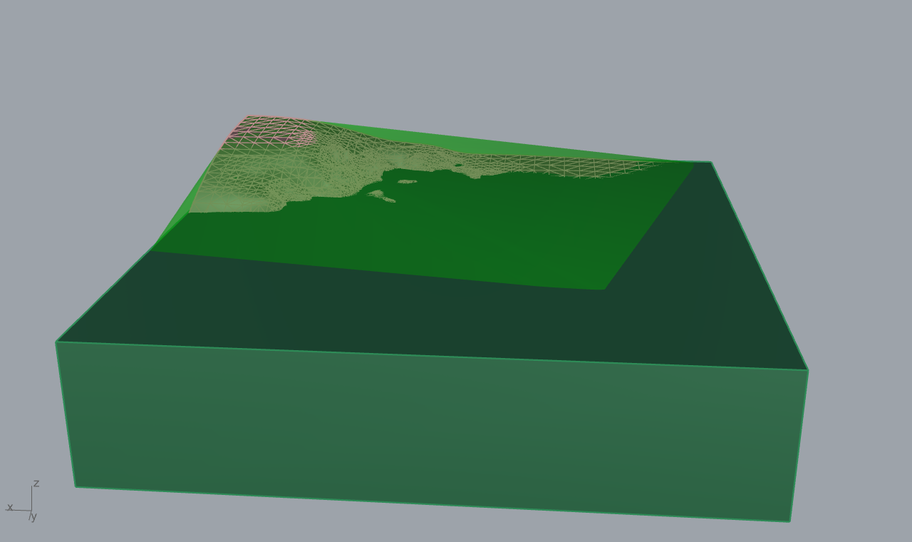
10.4.1 Screened Poisson reconstruction (original derivation)¶
Poisson reconstruction (Kazhdan, Bolitho, Hoppe 2006, [R90]; screened
variant Kazhdan and Hoppe 2013, [R91]) recovers a watertight surface from
oriented points by solving a single global Poisson equation. The insight is
that the oriented point samples are samples of the gradient of the model's
indicator function \(\chi\), which is 1 inside the solid and 0 outside. The
gradient of a step function is a surface delta carrying the inward normal, so
the point normals \(\mathbf{N}\), smeared into a vector field \(\vec V\) over an
adaptive octree, approximate \(\nabla\chi\). Recovering \(\chi\) is then the
variational problem of finding the scalar field whose gradient best matches
\(\vec V\):
whose Euler-Lagrange condition is the Poisson equation
The surface is then the isolevel of \(\chi\) at the average value it takes at the samples. The 2013 screened extension adds a positional data term so the surface is pulled back onto the points, not just made normal-consistent, turning the energy into
with the screening weight \(\beta\) tying the isosurface to the samples; this
removes the over-smoothing of the unscreened solve and sharpens detail at no
extra asymptotic cost. The octree depth controls resolution: the implementation
defaults to depth 8, typical range 7 to 9, with samples-per-node defaulting to
1.5 (ScanReconstructComponent.cs:78-83). The native call passes depth and
samples-per-node straight to PoissonRecon (ReconstructionNative.cs:85-92,
:236).
10.4.2 Numeric conditioning and crash isolation¶
Two repository deltas wrap the native call. First, recentering: before
reconstruction the cloud is translated to its centroid so the Delaunay and
alpha predicates evaluate near the origin, recovering mantissa digits at quarry
and UTM scale; normals are directions and are not translated; the centroid is
added back to the output vertices (ScanReconstructComponent.cs:250-256,
:319-320). This is the V3 numeric-hygiene rule applied at the reconstruction
boundary, and it is Rhino-free (GeometryNumerics is in Core).
Second, out-of-process isolation. OutOfProcessReconstructor writes the
cloud to a temp file, launches frahan_recon_worker.exe with the native shim
DLLs alongside it, and reads back a length-prefixed binary result guarded by a
'FREC' magic word (OutOfProcessReconstructor.cs:22, :122-171). A native
abort kills only the worker; the host detects it from the missing output magic
or a non-zero exit code and surfaces a clean managed error,
"the reconstruction backend faulted; Rhino is unaffected"
(OutOfProcessReconstructor.cs:75-80). If the worker exe is not deployed, it
falls back to the in-process (still FP-guarded) path with a note
(OutOfProcessReconstructor.cs:43-49). The component runs all this on a
background thread behind a default-false Run gate, so opening a definition
never triggers a reconstruction and the canvas never freezes
(ScanReconstructComponent.cs:25-30, :97-100). Finally the raw soup is
cleaned: the largest edge-connected component is kept and dangling alpha-shape
facets dropped (ScanReconstructComponent.cs:318-322).
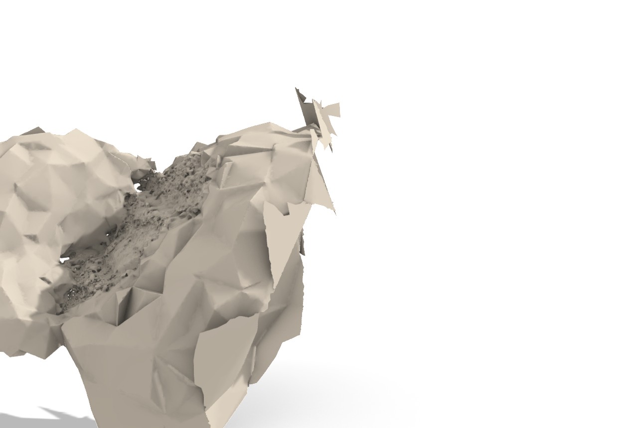
Originality. Scan Reconstruct and
ReconstructionNativeare wrapper-of-native over vendored-library backends: CGAL (alpha-shape, advancing-front, CGAL Poisson; GPL) and Geogram-bundled Kazhdan PoissonRecon (MIT, BSD-clean). The repository contributions are the recenter conditioning, the out-of-process crash isolation, the binary IPC, the async Run-gated wrapper, and the soup cleanup, none an algorithm. The[Algorithm]attributes cite Edelsbrunner-Mucke 1994, Kazhdan-Hoppe 2013, and Cohen-Steiner-Da 2004 correctly (ScanReconstructComponent.cs:32-37).
10.5 The managed fallbacks¶
When no native DLL is present, two managed kernels keep the plugin working.
MeshCsg is a pure-managed BSP-tree CSG: build a binary space partition per
input mesh, then implement Union, Intersection, and Difference as De Morgan
sequences of ClipTo and Invert on the two trees
(MeshCsg.cs:8-40). It is the silent fallback under CgalMeshBoolean when the
shim is absent (CgalMeshBoolean.cs:150-153, :226-236). It is a port of
Evan Wallace's csg.js (MIT) and the header says so (MeshCsg.cs:9-10). That
is a direct-port under a permissive licence and owes a THIRD_PARTY_NOTICES
attribution row, but no copyleft.
MeshRepair / Frahan Mesh Repair (GUID AB12C00A-...,
MeshRepairComponent.cs:37) is the Rhino-side weld / cull-degenerate /
heal-naked-edges / unify-normals pipeline, cited to the standard PMP reference
(Botsch et al. 2010, [R81]; MeshRepairComponent.cs:19). Mesh
Diagnostics (GUID AB12C005-...) is a read-only inspector over the same
reference (MeshDiagnosticsComponent.cs:18). Sanitize Mesh and Close Holes
front the CGAL and Geogram repair paths with a Geogram repair fallback
(MeshSanitizeComponents.cs:61-63).
Originality.
MeshCsgis direct-port (csg.js, MIT,MeshCsg.cs:9-10).MeshRepairComponentandMeshDiagnosticsComponentare facade-over-primitives composing RhinoCommon mesh operations behind a cited recipe (Botsch et al. 2010); they add no new algorithm, only the orchestration and the diagnostic readout (MeshRepairComponent.cs:19,MeshDiagnosticsComponent.cs:18).
10.6 Licensing posture (the load-bearing decision)¶
The whole-chapter mitigation is architectural: the default install ships no
native DLL and links no GPL, AGPL, or non-commercial code (originality matrix,
licensing register, flags E3/E5/E6). CGAL's PMP, simplification,
reconstruction, straight-skeleton, and partition packages are GPL and
depend transitively on GMP; they are reached only through the optional
frahan_cgal shim, with the managed BSP CSG (csg.js, MIT) as the in-tree
fallback. Geogram is BSD-3 and stays clean, but its TetGen path (needed for
volumetric Voronoi blocks) is AGPL and is OFF by default
(-DFRAHAN_WITH_TETGEN=OFF; GeogramMesh.cs:354-361). The Kazhdan PoissonRecon
bundled in Geogram is MIT and stays in the default path with attribution.
A commercial release would buy the CGAL commercial packages or stay on the
Geogram and managed paths only.
10.7 Status & what's left¶
- No native DLL in the default install. Every CGAL and Geogram operation in
this chapter is unavailable until the user builds
frahan_cgal/frahan_geogramfromnative/. The default experience is the managed BSP CSG plus the Rhino-side repair only. This is the licence mitigation, not a defect, but it is the single biggest gap between the documented capability and the out-of-box behaviour (AGENTS.md:19,CgalGeometry.cs:23-28). Severity: high. - CGAL/geogram components live on the
Labsubcategory, notMesh. The native shim wrappers (Mesh CSG (CGAL), Decimate (CGAL/Geogram), Segmentation, Skeleton, Remesh, Tetrahedralize) are filed underFrahan > Lab, while Repair, Diagnostics, Sanitize, Close Holes, and Scan Reconstruct are onMesh(CgalTestComponents.cs:133,MeshRepairComponent.cs:33). The tab split is a UX inconsistency, not a code fault. Severity: low. - TetGen AGPL gate. Volumetric Voronoi blocks (
VoronoiBlocks) and tetrahedralisation throw with a clear message when the shim is built BSD-clean (GeogramMesh.cs:354-361,:526-540). The volumetric-block pipeline is documented but unavailable in the default build. Severity: medium. - THIRD_PARTY_NOTICES owed. The csg.js port (
MeshCsg.cs:9-10), Geogram, and the bundled Kazhdan PoissonRecon all require attribution rows; noTHIRD_PARTY_NOTICES.mdwas at repo root at audit time (licensing register, flag 10). Severity: medium (provenance, not copyleft). - Figures are borrowed. This chapter's renders come from example 04 (Poisson bench), example 07 (scan-to-mesh), and example 15 (clean remesh); there is no dedicated CGAL-segmentation or straight-skeleton example render. Severity: low (documentation gap).
- No managed fallback for OBB / skeleton / partition / segmentation. These
are CGAL-only and throw when the shim is absent, by design
(
CgalGeometry.cs:14-16). A user without the shim cannot segment or skeleton a mesh at all. Severity: medium.
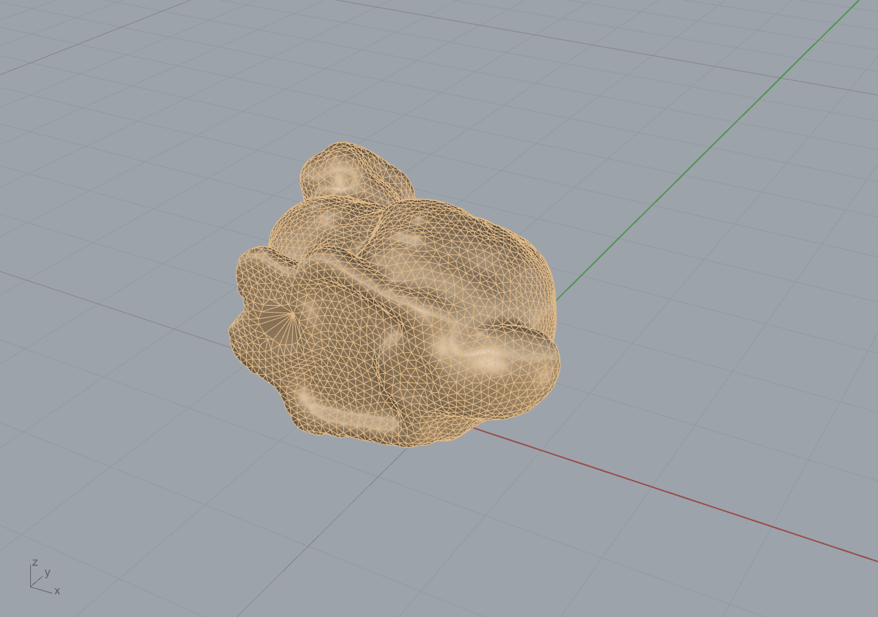
References (this chapter)¶
- Botsch, M., Kobbelt, L., Pauly, M., Alliez, P., Levy, B. (2010). Polygon mesh processing. AK Peters / CRC Press. ISBN 978-1568814261. [R81]
- Lloyd, S.P. (1982). Least squares quantization in PCM. IEEE Transactions on Information Theory 28(2):129-137. DOI 10.1109/TIT.1982.1056489. [R87]
- Edelsbrunner, H., Mucke, E.P. (1994). Three-dimensional alpha shapes. ACM Transactions on Graphics 13(1):43-72. DOI 10.1145/174462.156635. [R88]
- Kazhdan, M., Bolitho, M., Hoppe, H. (2006). Poisson surface reconstruction. Eurographics Symposium on Geometry Processing, pp 61-70. [R90]
- Kazhdan, M., Hoppe, H. (2013). Screened Poisson surface reconstruction. ACM Transactions on Graphics 32(3):29:1-29:13. DOI 10.1145/2487228.2487237. [R91]
- Cohen-Steiner, D., Alliez, P., Desbrun, M. (2004). Variational shape approximation. ACM Transactions on Graphics (SIGGRAPH 2004) 23(3):905-914. DOI 10.1145/1015706.1015817. [R92]
- Crane, K., Weischedel, C., Wardetzky, M. (2013). Geodesics in heat: a new approach to computing distance based on heat flow. ACM Transactions on Graphics 32(5):152. DOI 10.1145/2516971.2516977. [R95]
- Aichholzer, O., Aurenhammer, F. (1996). Straight skeletons for general polygonal figures in the plane. COCOON 1996, LNCS 1090, pp 117-126. [R96]
- Lindstrom, P., Turk, G. (1998). Fast and memory efficient polygonal simplification (quadric edge-collapse). IEEE Visualization '98, pp 279-286. [R97]
- Shapira, L., Shamir, A., Cohen-Or, D. (2008). Consistent mesh partitioning and skeletonisation using the shape diameter function. The Visual Computer 24(4):249-259. DOI 10.1007/s00371-007-0197-5. [R98]
- Levy, B. (INRIA/ALICE). Geogram: a programming library of geometric algorithms (v1.9.9). BSD-3. https://github.com/BrunoLevy/geogram. [R124]
- Wallace, E. csg.js (MIT). Constructive solid geometry via BSP trees. Ported
as the managed
MeshCsgboolean fallback.
11. Fabrication, Sculpting & Carving¶
This chapter covers the machine-handoff end of the repository: the
Fabricate ribbon tab (11 components) and the Sculpt ribbon tab (3
components). Where the earlier chapters turn rock into a valid cut or pack
plan, this chapter turns that plan into something a saw, a mill, or a
six-axis robot can run, and turns a scanned maquette into a carving schedule.
The subsystem is deliberately thin. Frahan's stated position is a pre-CAM
fabrication-readiness bridge, not a CAM system (docs/thesis/00_overview.md),
so the contribution here is parsing, frame construction, metadata carriage,
and a small amount of original scheduling math, not a toolpath optimiser.
Provenance in one line: the G-code path is clean-room parsing of a
published standard; the robot adapters are thin facades over third-party
plugins (KUKAprc, visose/Robots) that emit metadata and stop; the staggered
"Fabricate" flagship is a facade composing an in-repo layout primitive
with the CGAL boolean back end; the carving-stage and pointing-machine math
is clean-room original; and the georeferenced last-mile reuses the
clean-room geodesy and the Horn absolute-orientation kernel from Chapter
8. Every claim is anchored to a file:line, an [Algorithm] attribute, or a
worked example.
The Core types are pure-managed and Rhino-free
(src/Frahan.StonePack.Core/Fabrication, …/Sculpt); the Rhino dependency
lives only in the Grasshopper wrappers
(src/Frahan.StonePack.GH/Fabrication, …/Sculpt).
11.1 The G-code ingest path (clean-room parsing)¶
11.1.1 The modal state machine¶
A CAM post-processor emits ISO 6983-1 G-code (ISO 6983-1:2009): a line-by-line
program where motion words (G00/G01/G02/G03), coordinate words
(X Y Z, arc offsets I J K), and modal settings (G20/G21 units,
G90/G91 positioning, F feed, S spindle) accumulate state. The defining
property is modality: a line without a motion word inherits the previous
motion mode, and a bare X Y Z triple implies the last motion (the RhinoCAM
convention). GCodeParserComponent (GUID D5F10030, Frahan > Fabricate >
G-code Parser) implements exactly this as a single-pass tokenizer feeding a
modal state machine (GCodeParserComponent.cs:169-266).
Formally, the parser carries a state \(\sigma = (\mathbf{p},\ \text{mode},\ f,\ s,\ \text{abs},\ \text{mm})\) where \(\mathbf{p}\) is the current tool position. For each non-comment line \(\ell\) with parsed words \(W(\ell)\), the position update is the absolute/incremental branch
with ? denoting "use the word if present, else hold the prior component"
(GCodeParserComponent.cs:233-235). A CutSegment is emitted only when a
line carries motion, and its Start is the prior \(\mathbf{p}\) so segments
chain without gaps (:226-265). For an arc the centre is reconstructed from
the start point and the I J K offsets, the RhinoCAM-relative convention,
(:257-261). The parser is lossless on the supported subset and records every
unknown code as a warning rather than failing
(:296-303); G91 incremental positioning is parsed but flagged, since v1
solves only the G90 case it has fixtures for.
Originality. clean-room. The
[Algorithm]attribute names it an "ISO 6983-1 G-code tokenizer + modal state machine" credited to the ISO 6983-1:2009 standard and the observed RhinoCAM/VisualMill dialect, with the explicit note that the subset matches the MRAC IAAC 2023 workshop fixtures (GCodeParserComponent.cs:53-58). No upstream parser source is in the tree; the tokenizer is a single regex word-matcher (:333-349) and the state machine is the switch above. There is no copyleft exposure: the component reads a text file withSystem.Text.RegularExpressions.
11.1.2 G-code to tool-axis planes¶
GCodeToPlanesComponent (GUID D5F10031) translates the parsed CutPath
into the Plane[] representation that both downstream robot ecosystems
consume. The construction is a milling-frame convention: at each sample the
plane origin is the cut point, the plane \(Z\)-axis is the user tool axis
\(\hat{\mathbf{a}}\) (default \(-\hat{\mathbf{z}}\), downward milling), and the
plane \(X\)-axis is the segment direction projected perpendicular to the
tool axis,
with a world-\(X\) fallback when the segment runs parallel to the tool axis
(GCodeToPlanesComponent.cs:197-211). This Gram-Schmidt projection is the
load-bearing step: it guarantees an orthonormal right-handed frame whose
\(Z\)-axis is exactly the requested tool axis, regardless of how the cut
direction wanders, so the emitted target never tilts the spindle.
Arcs are discretised at an Arc Step chord length. The signed sweep is the
angle from start to end about the reconstructed centre, normalised by the
G02/G03 direction so a full circle (start == end) sweeps a full turn
rather than zero,
(:240-255). Each sample interpolates \(z\) linearly between the segment
endpoints (helix support) and sets the plane \(X\)-axis to the arc tangent,
signed by the sweep direction (:262-270). The chord error is bounded by
\(\text{ArcStep}/2\), the tolerance the [DesignApplication] attribute claims
(:49).
Originality. clean-room. Two
[Algorithm]attributes name the tool-axis frame construction ("standard milling-frame convention, tool axis = \(-Z\) by default") and the chord-step arc discretisation, both Frahan- original glue, with the note that CGAL arc primitives are deliberately not used (GCodeToPlanesComponent.cs:39-44). The math is elementary plane geometry; the contribution is the bridge shape, not an algorithm.
11.1.3 The robot adapters (thin facades, not toolpath generators)¶
PlanesToKukaPrcCommandsComponent (GUID D5F10032) and
PlanesToRobotTargetsComponent (GUID D5F10033) are the deliberate
honesty boundary of this subsystem. Each tags a Plane[] with the motion
metadata its target ecosystem expects and stops: it does not generate KRL
or simulate kinematics. The motion map is the only logic,
resolved per-plane by looking the source CutSegment.Kind up through the
segment-index list, defaulting all moves to the linear type with a warning
when the CutPath is not wired
(PlanesToKukaPrcCommandsComponent.cs:152-182;
PlanesToRobotTargetsComponent.cs:155-179). The Robots adapter additionally
converts feed units to that plugin's convention, \(\text{mm/s} =
\text{mm/min} / 60\), and widens the blending zone on rapid approaches
(PlanesToRobotTargetsComponent.cs:170-177).
The market rationale is recorded in the headers: KUKAprc's Generic NC Import
is a paid-tier feature, and visose/Robots has no native G-code ingest at all,
so the GCodeParser plus these wrappers is the first free open-source path
from a CAM .nc file into either ecosystem
(PlanesToKukaPrcCommandsComponent.cs:28-31;
PlanesToRobotTargetsComponent.cs:19-23).
Originality. facade-over-primitives / wrapper. Both are thin wrappers credited to KUKAprc (Brell-Cokcan and Braumann) and visose/Robots (Soler, MIT v1.9.0); the only original logic is the
CutSegmentKindto motion mapping, named Frahan-original in the[Algorithm]attributes (PlanesToKukaPrcCommandsComponent.cs:40-42;PlanesToRobotTargetsComponent.cs:40-42). Neither linksRobots.dll(PlanesToRobotTargetsComponent.cs:30-37), so there is no licence ingress.
11.2 The wire-saw toolpath adapter (bottom-up flagship)¶
WireSawToolpathAdapterComponent (GUID D5F10034) generates a Plane[]
toolpath for a robot-mounted diamond-wire saw cutting along a designed curve.
The v1 algorithm samples \(N\) frames along the cut curve: at parameter \(t\) the
origin is the curve point, the \(Z\)-axis is the user wire-tension axis
\(\hat{\mathbf{w}}\), and the \(X\)-axis is the curve tangent projected
perpendicular to the wire,
the same Gram-Schmidt frame as the milling case but with the wire axis taking
the role of the tool axis (WireSawToolpathAdapterComponent.cs:200-218).
Original derivation: kerf compensation¶
A diamond wire removes a finite-width channel. If the wire traces the design curve, the finished cut surface sits half a kerf inside the intended boundary on each side. To make the finished surface match design intent, the adapter offsets the cut curve outward by half the kerf width before sampling,
in the curve's own plane, falling back to no compensation with a warning on a
non-planar curve (:174-192). The half-kerf magnitude is taken from the
closest published precedent: Zhang et al. (2024) report a kerf compensation
\(\Delta = 1.75\ \text{mm}\) for a brazed-diamond wire on a six-axis robot that
carved a Stanford Bunny in marble at 2.30x the speed of grinding; the
component cites this verbatim and defaults to a \(4\ \text{mm}\) mid-range kerf
(:54-56, :101-104, :225-227). Diamond-wire kerf (3 to 8 mm) is markedly
tighter than blade-saw kerf (10 to 15 mm), which is why the compensation
matters at sculpture scale.
Originality. clean-room glue over a cited precedent. Three
[Algorithm]attributes carry the provenance: Zhang et al. (2024, J. Computational Design and Engineering 11(6), DOI 10.1093/jcde/qwae094) and Moult, Weir and Fernando (2018, University of Sydney) as the robot-mounted diamond-wire precedents, and the kerf-compensated curve offset as Frahan-original glue over classical RhinoCommonCurve.Offset(WireSawToolpathAdapterComponent.cs:54-62). The header is careful about the honesty boundary: Quarra used a stationary rented quarry wire saw, not an end-effector; Gramazio Kohler "Spatial Wire Cutting" is hot-wire on foam, not diamond-wire on stone; and neither published precedent ships a KUKAprc/Robots integration, so this is the first GH bridge for the workflow (:31-35). The robot-mounted diamond-wire workflow itself is research-grade, stated plainly in the remarks (:233-236). The distinct robot-diamond-wire Zhang (2024) must not be conflated with the block-cutting MATLAB toolbox of Zhang et al. (2024) cited elsewhere in the references; they are different works.
11.3 The staggered-masonry "Fabricate" flagship¶
The flagship niche is the inverse of masonry assembly: take a sculpted,
freeform stone form and split it into staggered, running-bond-like blocks,
each sized to be cut by wire saw and finished by robotic milling
(StaggeredBlockLayout.cs:7-24). StaggeredBlockDecomposeComponent (GUID
F2D07A02) lays the cells out over the form's bounding box and emits them as
boxes plus box-meshes plus a per-cell course index (ascending = build order).
The running-bond cell layout¶
The Core layout (StaggeredBlockLayout.Build) tiles the box
\([\mathbf{lo},\mathbf{hi}]\) in three axis roles chosen automatically: the
up axis (course stacking, default \(Z\)), the bond axis (the larger of
the two remaining axes), and the depth axis spanning a single wythe
(StaggeredBlockLayout.cs:62-67). Course \(c\) occupies the up-axis band
\([u_0,u_1]\) at height \(h_c\), and within it the bond axis is tiled at block
length \(L_b\) with the odd-course half-block stagger that breaks the
joints,
with \(s = 0.5\) the running-bond default (:74-86). Each cell is clamped to
the box so the boundary courses are not over-tiled
(\(cx_0 = \max(b_{\text{lo}}, x)\), \(cx_1 = \min(b_{\text{hi}}, x + L_b)\),
:88-90). The header is explicit that this is not the infinite-plane
BrickPattern generator: that emits planes whose single cut pass yields a
regular grid, whereas this class produces explicit per-course cells with the
stagger already applied, the per-course post-processing that turns a grid into
a true running bond (:13-21).
The component deliberately does not fan out \(N\) RhinoCommon mesh booleans, the
documented HITL failure mode on large slabs. To get form-fitted blocks the
user pipes the cell meshes into the CGAL/geogram back end (Quarry Decompose
By Mesh (CGAL) or Mesh CSG (CGAL)), which scales to many cuts
(StaggeredBlockDecomposeComponent.cs:22-26, :42-44). This is the
"compose, don't duplicate" rule (Chapter 14): the cell layout is the new
contribution, the cutting is an existing primitive.
Originality. facade-over-primitives. The cell layout is named Frahan-original in the
[Algorithm]attribute, with the honest note that running bond is a masonry convention, not a citable algorithm (StaggeredBlockDecomposeComponent.cs:33-34). The component composes the pure-managedStaggeredBlockLayoutwith the CGAL boolean back end it routes to; it adds orchestration, not a new algorithm. Two downstream consumers complete the flagship:FabricationPrepReportComponent(below) for handling, and theStoneCutExportmetadata carriage (11.4).
11.4 Stone-aware cut export and fabrication-prep handling¶
Carrying stone intelligence through the CAM handoff¶
CAM packages (EasySTONE, Alphacam, Breton Maestro, Lantek) consume .3dm and
DXF geometry, but they receive it as dumb shapes; the bed and grain direction,
the fracture/GPR avoidance zones, the quarry-block provenance, the weight, the
finish and the kerf are lost at the handoff and re-keyed by hand on the shop
floor. StoneCutMetadata is the payload that survives the handoff: a
namespaced set of object user-strings (frahan.piece_id, frahan.stone,
frahan.bed_dir, frahan.kerf_mm, …) stamped with a schema tag
frahan-cut-1.0 so a CAM round-trip cannot silently clobber it
(StoneCutMetadata.cs:42-75). StoneCutExportComponent (GUID F2D07A01)
writes one .3dm layer per cut piece with that metadata attached, gated
behind a default-false Write toggle, the same side-effect discipline as the
async Run gates elsewhere (StoneCutExportComponent.cs:28-30, :107-163).
Originality. clean-room glue. The metadata schema and the layer scheme are Frahan-original conventions; the writer is RhinoCommon
File3dmplusSetUserString. There is no algorithm here, only a structured carriage contract, which is the point: the wedge is owning the upstream intelligence and refusing to drop it at the machine boundary (StoneCutMetadata.cs:10-22).
Weight and lift class from the cut¶
FabricationReport turns block geometry into shop-floor handling facts. The
weight is volume times density, and the lift class follows from a fixed
threshold ladder (FabricationReport.cs:30-40),
with a granite default \(\rho = 2700\ \text{kg/m}^3\). FabricationPrepReport
(GUID F2D07A04) computes per-block volume and centroid through RhinoCommon
VolumeMassProperties, warns when a block is not closed (volume unreliable),
and reports the per-class histogram so the crate and hoist plan follows from
the cut (FabricationPrepReportComponent.cs:83-112). The model-units-are-
metres assumption is stated, since the same volume number is metres-cubed
only under that convention.
Originality. clean-room. Elementary mass-properties arithmetic over a RhinoCommon volume; the lift ladder is a handling convention, and the contribution is closing the fabrication-prep market gap, not an algorithm (
FabricationReport.cs:6-11).
11.5 The digital pointing machine (Sculpt tab)¶
The classical pointing machine is the sculptor's tool for transferring and
scaling a maquette to a full-size carving by measuring a few reference
points and reproducing depths. The Sculpt tab is its digital equivalent in
three nodes: enlarge a scanned maquette, verify it fits an available block,
and schedule the roughing passes.
11.5.1 Enlargement (affine scale from the base)¶
EnlargeSculptureComponent (GUID F2D06A01) scales a scanned maquette to a
target size in four modes. The per-axis factors are pure arithmetic on the
current bounding size \((s_x,s_y,s_z)\) (SculptureFitter.EnlargeFactors,
SculptureFitter.cs:47-81),
The GH wrapper applies the scale about an anchor that defaults to the base
centre (bbox centre in \(X,Y\) at minimum \(Z\)), so a plinth stays grounded as
the piece grows, and warns when a non-uniform scale changes proportions
(EnlargeSculptureComponent.cs:98-125).
11.5.2 Does it fit the block?¶
FitInBlockComponent (GUID F2D06A02) answers whether a raw block holds an
enlarged sculpture, allowing a margin for kerf, roughing allowance and
handling. The test sorts both extent triples descending (largest axis to
largest axis, the best box-aligned orientation), subtracts a two-sided margin
from the block, and reports per-axis slack plus the largest uniform scale that
would still fit (SculptureFitter.FitsInBlock, SculptureFitter.cs:91-114),
where \(b_{(i)}, s_{(i)}\) are the sorted block and sculpture extents. The
max-scale-to-fit \(\sigma_{\max}\) is the binding ratio across axes; \(\sigma_{\max}\ge1\)
means the piece already fits. v1 is axis-aligned; an OBB-exact orientation
search is a stated later refinement (FitInBlockComponent.cs:18-21).
Originality. clean-room. Both nodes are pure affine arithmetic with
[Algorithm]attributes naming them Frahan-original "digital pointing- machine tradition; affine scale, not a published algorithm" and "axis- aligned bounding extents matched largest-to-largest" (EnlargeSculptureComponent.cs:25-26;FitInBlockComponent.cs:28-29). The Core math is inSculptureFitter, runtime-agnostic and unit-tested in isolation from Rhino.
11.5.3 Carving stages: the roughing schedule (original derivation)¶
A carver removes stock in steady passes, not one cut. The digital equivalent
is a stack of offset shells from the rough block down to the finished surface.
CarvingStages.OffsetSchedule is the pure schedule: \(K\) outward offsets
stepping linearly from a coarse maxOffset (stage 0, roughest) down to a
finishAllowance (last stage, the finish surface),
so \(d_0 = d_{\max}\) and \(d_{K-1} = d_{\text{finish}}\), with the single-stage
case collapsing to the finish allowance (CarvingStages.cs:25-39). This is a
linear interpolation in offset distance, the simplest monotone roughing ladder
that leaves a controlled finish skin.
CarvingStagesComponent (GUID F2D06A03) realises each shell as a per-vertex
offset of the target mesh. Three modes select the offset direction: Radial
(along smoothed surface normals), Push-In (along a front direction), and
Flat-Top (push each vertex up to the bounding-box face, best for reliefs).
A Block input clamps each stage to an arbitrary scanned block by casting a
per-vertex ray against an RTree of the block faces, so the reach is the
distance to the real block surface rather than an AABB
(CarvingStagesComponent.cs:186-205, RayBlockReach :279-293). For the
block/flat-top modes the stage shell at fraction
\(\mathrm{frac}_s = 1 - s/(K-1)\) moves each vertex
\(\mathbf{v}_v \mapsto \mathbf{v}_v + \mathrm{frac}_s\,r_v\,\hat{\mathbf{d}}_v\)
along its reach \(r_v\) (:206-218), so stage 0 sits at the block and the final
stage at the target.
Original derivation: the fold-fix. A naive per-vertex normal offset folds
onto itself at sharp edges and thin rims, producing spikes on reliefs. The
component applies two corrections from the 2026-05-30 "v2" work, kept after
the synchronous restore. First, the offset uses Laplacian-smoothed normals
\(\tilde{\mathbf{n}}_v\), averaged over topology neighbours for a fixed iteration
count (SmoothNormals, :342-374). Second, each offset is capped at half
the shortest edge incident on the vertex,
(LocalOffsetCaps, :378-403, applied :236, :243), which guarantees no
vertex crosses its nearest neighbour, the geometric condition for a non-folding
offset. A protrusion weight boosts stock at the strongest protrusions
(ears, noses) by \(d_v(1 + \text{boost}\cdot w_v)\) where \(w_v\) is the normalised
outward displacement of a vertex from its neighbour centroid (ProtrusionWeights,
:314-339).
The scheduling discipline (synchronous + cached, decimate-first). The
component was restored to a synchronous, input-cached, Run-gated design after
a v2 rewrite dropped the cache and reordered the inputs: every canvas edit then
recomputed, and on a 2.2-million-vertex scan that is roughly 11 seconds per
change, a frozen canvas (:18-23). The fix is caching, not threading: the
component recomputes only when a proxy hash of its own inputs changes (counts,
bounding box, parameters), and on any other canvas solution (picking a List
Item index, editing an unrelated node) it re-emits the cached stage meshes
without recomputing (:119-152, BuildHash :260-275). An always-on
background re-solve would recompute every pass, exactly what is being avoided
(:38-41). Input order matches files saved under the proven commit so old
canvases re-wire correctly, and the input order must not be changed again.
Preview is off by design: redrawing all \(K\) dense shells every viewport
refresh is what bogged the canvas, so the intermediate shells are picked
downstream with a List Item (:42-45). The companion rule is decimate
first: never internalise a multi-million-vertex scan in a saved .gh
(autosave crash, KB-1), and reduce a raw scan to roughly 150k vertices before
carving (examples/05_artist_pointing_machine/README.md).
Originality. clean-room. The
[Algorithm]attribute names it "Staged offset-shell roughing", Frahan-original, with the honest note that it is pure per-vertex offset math, \(O(\text{vertices}\times\text{stages})\), and that no published roughing-strategy paper is implemented (CarvingStagesComponent.cs:53-54). The Core schedule is the linear ladder above; the GH fold-fix (smoothed normals + neighbour cap) is the small clean-room delta that makes it usable on real scans.
11.6 The georeferenced last-mile (physical marking)¶
The marble cost study (Chapter 3, example 08) leaves a gap: the optimiser produces oblique, bed-following cutting planes that recover more value than flat guillotine cuts, but realising them needs the cut planes marked on the physical block in the correct place. The last-mile is georeferencing: tie the scan frame to surveyed world control points so a cut plane computed in the model lands on the real stone.
GeoreferenceMath is the pure-managed geodesy that places a scan in a metric
world frame. It carries the WGS84 ellipsoid, the closed-form Bowring (1976)
LLH-to-ECEF transform and its non-iterative inverse, the ECEF-to-ENU rigid
rotation about a chosen origin, and the Karney (2011) transverse-Mercator UTM
series truncated to order six (GeoreferenceMath.cs:62-105, :113-159,
:169-283). The east-north-up rotation about an origin at latitude
\(\varphi_0\), longitude \(\lambda_0\) is the standard
(GeoreferenceMath.cs:130-132). Working in a metric ENU frame removes the
scale ambiguity, so the rigid solve downstream is well-posed.
The rigid scan-to-world fit is the three-point (N >= 3) absolute
orientation the prompt calls for. GeoreferenceComponent (GUID
B1C2D3A4-…) converts the world control points to ENU about the first
point, then calls RegistrationApi.SolveFromPoints, which solves
in closed form via the Horn (1987) unit-quaternion method
(RegistrationApi.cs:68-108; consumed at GeoreferenceComponent.cs:158).
The closed-form recipe is the classical one: subtract the centroids
\(\bar{\mathbf{s}},\bar{\mathbf{w}}\), build the cross-covariance, extract the
optimal rotation as the eigenvector of the symmetric \(4\times4\) quaternion
matrix, and recover the translation
\(\mathbf{t} = \bar{\mathbf{w}} - R\,\bar{\mathbf{s}}\). Three non-collinear
pairs are the minimum, exactly the pointing-machine reference-point count. The
component reports the RMS residual and flags any control point whose residual
exceeds five times RMS as a possibly mis-tagged GPS fix
(GeoreferenceComponent.cs:172-179), and it returns the ENU origin LLH so a
downstream graph can re-create the identical projection frame
(:96-102).
Originality. clean-room. The geodesy is a pure-managed implementation of published transforms (Bowring 1976, Karney 2011, with Snyder 1987 as the working-manual reference), with zero third-party dependencies (
GeoreferenceMath.cs:6-27). The rigid fit reuses theRigidTransformRecoveryHorn (1987) kernel already classed clean-room in Chapter 8, here exposed through a Rhino-friendly facade (RegistrationApi.cs:9-29); the[Algorithm]attribute credits Horn 1987 by DOI (GeoreferenceComponent.cs:36). The Horn kernel is one of three duplicate absolute-orientation routes in the tree, a noted low-severity refactor candidate (Chapter 8).
The georeferenced bed-following recovery is real but its physical-marking
tail is not yet a shipped component. Example 08 measures the value at stake:
on the 6 m marble bench the flat guillotine plan is fabricable today, while
the oblique bed-following plan recovers materially more value but requires the
georeferenced marking step that this section's math enables and that no GH
component yet automates (examples/08_gpr_marble/README.md; the cost study is
documented in Chapter 3).
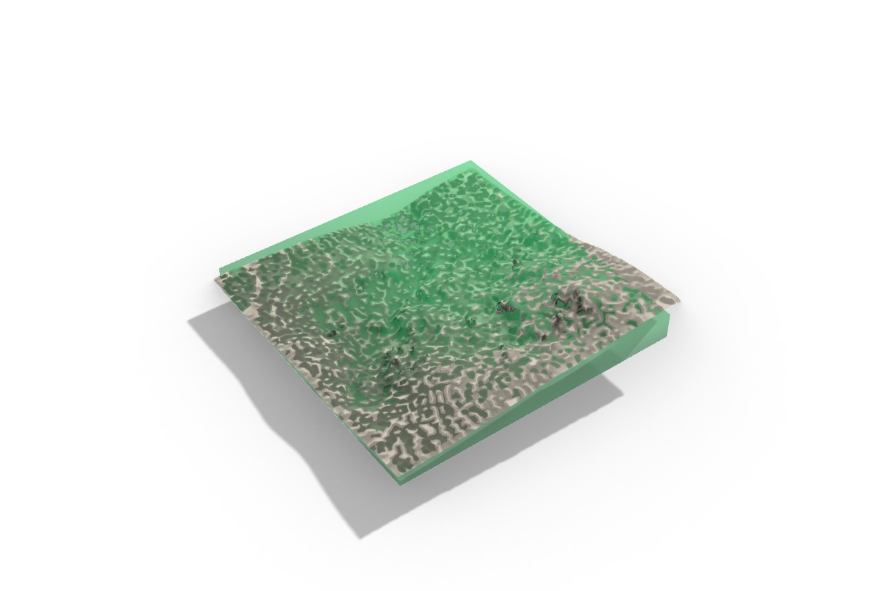
11.7 Status and what is left¶
- Example 05 has no rendered figure. The artist pointing-machine folder
ships the carving-stages
.ghand a light.3dm/.ghsimulation only, no PNG and no embeddable render (examples/05_artist_pointing_machine/). The figures in this chapter borrow from the engineer (04), guillotine (24), marble cost (25), and GPR marble (08) examples. Low (documentation gap). - Physical-marking tail not shipped. The georeferenced math (11.6) closes the scan-to-world transform, but no GH component yet turns the oblique bed-following cut planes into a georeferenced physical-marking output on the real block; example 08 documents the value the last-mile recovers but the automation is open. High (the named last-mile of example 08).
- Wire-saw v1 is planar only. Kerf compensation is skipped on a
non-planar cut curve (warned), and curved-surface cuts via ruled-surface
decomposition, variable wire tension, and bidirectional planning are v1.x
backlog (
WireSawToolpathAdapterComponent.cs:46-52,:188-191). The robot-mounted diamond-wire workflow remains research-grade per Zhang 2024 and Moult 2018. Medium. - G-code parser subset. v1 supports
G00/G01/G02/G03/G17/G20/G21/G90plusF S M N;G91incremental positioning andG18/G19non-XY arc planes are parsed but flagged, not solved (GCodeParserComponent.cs:296-303). Vendor extensions are deferred. Low (graceful warnings, not failures). - Robot adapters depend on third-party plugins. The KUKAprc command
components are paid-tier, and the visose/Robots plugin must be installed
separately (Frahan does not bundle
Robots.dll); the packaging decision is open (PlanesToRobotTargetsComponent.cs:30-37). Low. - Fit-in-block is axis-aligned. v1 matches sorted extents largest-to-
largest; a sculpture that fits only in a tilted orientation is reported as
not fitting. OBB-exact orientation search is deferred
(
FitInBlockComponent.cs:18-21). Low. - Carving Stages input order is load-bearing. Reordering the inputs breaks
canvases saved against the proven layout (the v2 regression); the order must
stay frozen, and heavy scans must be decimated before carving (KB-1/KB-2)
(
CarvingStagesComponent.cs:18-23;examples/05_artist_pointing_machine/README.md). Medium.
References (this chapter)¶
- ISO 6983-1:2009. Automation systems and integration — Numerical control of machines — Program format and definitions of address words — Part 1: Data format for positioning, line motion and contouring control systems. International Organization for Standardization.
- Horn, B.K.P. (1987). Closed-form solution of absolute orientation using unit quaternions. Journal of the Optical Society of America A 4(4):629-642. DOI 10.1364/JOSAA.4.000629. (Reference key [R103].)
- Zhang, Y., Wu, H., Wang, J., et al. (2024). Robotic diamond-wire cutting of stone with a six-axis arm and end-effector wire saw. Journal of Computational Design and Engineering 11(6):75-85. DOI 10.1093/jcde/qwae094. (Robot-mounted diamond-wire precedent; distinct from the block-cutting MATLAB toolbox Zhang et al. 2024, reference key [R145].)
- Moult, S., Weir, J., Fernando, S. (2018). Robotic diamond-wire bandsaw cutting of stone with a portable end-effector. University of Sydney (proceedings reference, cited in source).
- Konstanty, J.S. (2021). The mechanics of sawing granite with diamond wire. International Journal of Advanced Manufacturing Technology 116:2591-2597. DOI 10.1007/s00170-021-07577-3. (Diamond-wire kerf mechanics; reference key [R27].)
- Bowring, B.R. (1976). Transformation from spatial to geographical coordinates. Survey Review 23(181):323-327. DOI 10.1179/sre.1976.23.181.323.
- Karney, C.F.F. (2011). Transverse Mercator with an accuracy of a few nanometres. Journal of Geodesy 85(8):475-485. DOI 10.1007/s00190-011-0445-3.
- Snyder, J.P. (1987). Map Projections: A Working Manual. USGS Professional Paper 1395.
- Graham, R.L. (1969). Bounds on multiprocessing timing anomalies. SIAM Journal on Applied Mathematics 17(2):416-429. DOI 10.1137/0117039. (Greedy list scheduling, cited by the fabrication-prep handling lineage.)
- Braumann, J., Brell-Cokcan, S. KUKA|prc — parametric robot control for Grasshopper. Association for Robots in Architecture, Vienna. https://www.robotsinarchitecture.org/kukaprc
- Soler, V. Robots — a plugin for programming industrial robots in Grasshopper (MIT). https://github.com/visose/Robots
12. Data Ingestion & Format Readers¶
This chapter covers the repository's data-ingestion subsystem: the Ingest
ribbon tab (5 components), the Frahan.Masonry.Quarry.Ingestion reader family
in the Core assembly, and the Frahan.Core.ScanIngest point-cloud readers and
out-of-process workers. The subsystem is the front door of the whole pipeline.
Every downstream chapter (nesting, quarry block-cutting, masonry, surface
packing, edge-matching) consumes geometry that entered the repository through a
reader documented here.
The design goal stated across the source is max-coverage ingest: read the formats a stone-fabrication site actually produces, route each by file extension to a dedicated reader, and never guess a proprietary binary layout. The reader set spans vector fracture data (ESRI Shapefile, GeoJSON), terrestrial LiDAR and photogrammetry point clouds (E57, LAS/LAZ, PLY, XYZ), and ground-penetrating-radar radargrams (CSV, SEG-Y, MALA RD3, pulseEKKO DT1, IDS GeoRadar DT, GSSI DZT). Where a format is proprietary with no open spec, the reader is a deliberate dead-stop that tells the user how to convert, rather than a silent corruptor of the depth axis.
This chapter is mostly engineering, not new mathematics: a reader's job is to
decode a documented byte layout faithfully. The two places real derivation
appears are the GPR sample-spacing recovery (turning a time axis into a metric
depth axis) and the streaming voxel-downsample (bounding memory by occupied
voxels, not input point count). Where a component merely wraps a third-party
library, it is named vendored-library or wrapper-of-native by its
upstream and licence, per the originality scheme of 90_originality.md. The GPR
processing chain itself (migration, Hilbert energy, fracture extraction) lives
in chapter 4; this chapter stops at the clean radargram, point cloud, or
polyline the readers emit.
12.1 The ingestion architecture¶
The subsystem is two-layered, matching the Rhino-free Core convention. A pure
managed reader in Frahan.Masonry.Quarry.Ingestion or Frahan.Core.ScanIngest
parses bytes to a plain POCO (a GprRadargram, a FractureTraceCollection, a
flat xyz array); a thin Grasshopper component in the Ingest tab adapts that
POCO to RhinoCommon geometry on the canvas. No reader references RhinoCommon, so
all parsing is unit-testable headless and a format can be exercised without
Rhino running. The five canvas components in the Ingest subcategory are GPR
File Loader, GPR Radargram Mesh, GPR Picks From Points, Vector Fractures Loader,
and Import Photo Markers; the point-cloud readers (Load E57 Cloud, Read LAS/LAZ
Cloud) are filed under the Mesh subcategory but share the same ingestion
contract and are covered here.
Three rules govern every reader and are visible throughout the source.
Dispatch by extension, single entry point. GprFileReader.Load and
VectorFractureReader.Load are switch statements over the lowercased file
extension that route to the matching format reader, so the canvas component does
not have to know whether the user dropped a .shp or a .geojson, a .rd3 or a
.dzt (GprFileReader.cs:30-56, VectorFractureReader.cs:21-32).
Never bulk-pipe raw samples to the canvas. A radargram can carry millions of
int16 amplitudes and a LiDAR scan hundreds of millions of points. Piping that
through a Grasshopper data tree crashes the document (KB-1, the large-mesh
autosave trap). The GPR File Loader therefore emits only trace-origin points,
counts, and spacing, and documents that per-sample access goes through the Core
reader directly (GprFileLoaderComponent.cs:28-33). The point-cloud readers
assemble exactly one PointCloud object, never thousands of loose points
(LoadE57CloudComponent.cs:21-23).
Bridge, do not guess. A proprietary container with no open binary spec is refused with an actionable error, not parsed on a guess (section 12.5).
12.2 Vector fracture readers (Shapefile / GeoJSON)¶
Fracture-trace data from UAV photogrammetry and field mapping arrives as ESRI
Shapefiles or GeoJSON. VectorFractureReader dispatches .shp to
ShapefileFractureReader and .geojson/.json to GeoJsonFractureReader,
both of which delegate the actual format parsing to NetTopologySuite.IO.Esri
and NetTopologySuite.IO.GeoJSON (ShapefileFractureReader.cs:5-6,34,
GeoJsonFractureReader.cs:5-7,34).
The reader's own work is the geometry-to-trace mapping, not the byte decode. It
walks each feature's Geometry: a LineString becomes one FractureTrace (its
Coordinate[] projected to 2-D TracePoint2D vertices), and a
MultiLineString recurses into its parts; points and polygons are silently
skipped, because this reader is for linear fracture traces specifically
(ShapefileFractureReader.cs:45-67). The feature attribute table is flattened
to a string-keyed dictionary and carried on each trace, so per-trace metadata
(aperture, set id, confidence) survives ingest
(ShapefileFractureReader.cs:80-91).
Coordinate reference handling is deliberately conservative. The companion .prj
is read verbatim into CrsWkt and stored, but the reader does not reproject;
the caller decides whether a Loviisa file in EUREF_FIN_TM35FIN metres needs
transforming (ShapefileFractureReader.cs:31,93-105,
VectorFracturesLoaderComponent.cs:29-32). GeoJSON carries no CRS under RFC 7946,
so its CrsWkt is empty and the file is assumed already in the desired frame
(GeoJsonFractureReader.cs:11-19). This is the correct posture: a reader that
silently reprojected would introduce a datum error invisible to the user.
The Vector Fractures Loader component (VecFrac, GUID
F2D00BEC-2026-4522-B0B0-1ABE15A0DEAD) emits one open PolylineCurve per trace
in source CRS units, plus the CRS WKT, the trace count, and the attribute keys
and values as parallel {trace_index} data trees
(VectorFracturesLoaderComponent.cs:65-83,104-129).
Originality. vendored-library. Both vector readers are thin adapters over NetTopologySuite.IO.Esri and NetTopologySuite.IO.GeoJSON; only the geometry-to-
FractureTracemapping and the.prjcarry-through are ours. The[Algorithm]attribute names the standard explicitly: "ESRI Shapefile / OGC Simple Features (standard) ... industry format via NetTopologySuite.IO.Esri; not a paper" (VectorFracturesLoaderComponent.cs:38-39). NetTopologySuite is permissively licensed (BSD-3-style); attribution is owed inTHIRD_PARTY_NOTICES, no copyleft (NTS 2023). This is also covered from the fracture-mapping angle in chapter 4.
12.3 Point-cloud readers and the streaming voxel downsample¶
The point-cloud path targets two scan modalities: registered terrestrial LiDAR
(E57, LAS/LAZ) and photogrammetric dense clouds (PLY, XYZ/PTS). The shared
problem is size: a single airborne tile in this corpus is a 357-million-point
LAZ. Materialising that as a full double[] would exhaust memory before any
downstream step runs. The repository's answer is a streaming voxel hash-grid
that reduces during the read.
12.3.1 The streaming voxel grid¶
StreamingCloudReader reads PLY (binary and ASCII) and plain XYZ/PTS forward,
one point at a time, folding each straight into a VoxelGridSink
(StreamingCloudReader.cs:10-32). The sink keys each point by its integer voxel
index and accumulates a running centroid:
with \(v\) the voxel edge length. The grid stores one \((\text{sum}, \text{count})\)
pair per occupied voxel and emits one centroid per occupied voxel at the end. The
key observation is that peak memory is bounded by the number of occupied
voxels, not the input point count: a forward-only stream never builds a full
array of all input points, so a 28-million-point file collapses straight into
the grid as it streams (StreamingCloudReader.cs:14-17,25-27). The same hash
key matches VoxelDownsampleComponent.ManagedVoxelDownsample, so the streaming
path and the in-memory path agree centroid-for-centroid.
The compressed-LiDAR reader LazCloudReader wraps Unofficial.laszip.net, a
pure-managed C# port of LASzip (Isenburg 2013) that reads both uncompressed
.las and compressed .laz on net48. It streams points one at a time straight
into the same VoxelGridSink, so a 357-million-point LAZ reduces to a manageable
centroid cloud with memory bounded by occupied voxels
(LazCloudReader.cs:9-31,41-55). laszip_get_coordinates applies the LAS
header scale and offset internally, so the doubles handed to the sink are already
real-world UTM coordinates, equivalent to
with header scale \(\mathbf{s}\) and offset \(\mathbf{o}\)
(LazCloudReader.cs:18-20).
Originality.
StreamingCloudReaderand theVoxelGridSinkcentroid grid are clean-room (elementary spatial-hash quantisation; the PLY header parse follows the same byte-level approach as the mesh reader).LazCloudReaderis vendored-library: laszip.net (LGPL-style, net48-compatible) does the LAS/LAZ decode; only the stream-into-voxel-sink wiring is ours (Isenburg 2013; ASPRS LAS 1.4). PLY format per Turk 1994; the XYZ/PTS path is a plain ASCII scan.
12.3.2 The E57 out-of-process worker¶
E57 (ASTM E2807-11) is the standard registered-terrestrial-LiDAR exchange format, and it is the hardest ingest in the subsystem for two reasons: there is no managed .NET E57 reader, and parsing a multi-GB scan in-process inside Rhino risks both an out-of-memory condition and a native fault that takes down the host. The repository solves both with an out-of-process worker.
Load E57 Cloud (GUID E4F5A6B7-3230-4F5E-A6B7-C8D9E0F12345) shells out to a
Python worker, frahan_e57_worker.py, that uses pye57 + numpy to read the
scans, voxel-downsample, and write a compact binary-little-endian PLY; the
component then reads that PLY back in chunks and assembles a single
PointCloud (E57CloudWorker.cs:27-37, LoadE57CloudComponent.cs:13-31). This
mirrors the same pattern used for surface reconstruction
(OutOfProcessReconstructor) and subprocess fracture detection: a crash kills
only the worker, never Rhino. The worker is launched with redirected stdout and
stderr, a 600-second timeout, and a PROGRESS line protocol surfaced as
component status; a SUMMARY line carries the all-numeric result that the C#
runner parses without a JSON dependency (E57CloudWorker.cs:52-128,131-159).
The worker's voxel downsample is a pure-numpy sort-reduce: it encodes each
point's per-axis voxel index (offset to non-negative) into one int64 linear
key, sorts, and segment-reduces with np.add.reduceat, so only the cloud extent
drives the key range and large UTM coordinates are fine
(frahan_e57_worker.py:37-59). The per-scan downsample is followed by a final
merge-and-downsample pass so voxels straddling scan boundaries collapse
correctly (frahan_e57_worker.py:122-125).
The coordinate shift (precision derivation). PLY stores coordinates as
float32, which carries about 24 bits of mantissa, roughly 7 significant decimal
digits. A projected UTM coordinate is order \(10^6\) metres, so a raw float32
store would resolve only to about \(10^6 / 10^7 = 0.1\) m, far coarser than a
scan's sub-millimetre detail. The worker therefore subtracts an integer-metre
global offset (the floor of the bounding-box minimum) before the float32 cast,
so the stored magnitudes are bounded by the cloud's extent (tens to hundreds of
metres), where float32 keeps sub-millimetre accuracy
(frahan_e57_worker.py:127-131, E57CloudWorker.cs:11-25). The shift is
reported back as the component Shift output; adding it to the cloud restores
the georeferenced position, so precision and georeferencing are both preserved
(LoadE57CloudComponent.cs:87-90,216-224). Bounds are reported in the original
unshifted frame.
The component is non-blocking: it derives from AsyncScanComponent with a
default-false Run gate, so the worker run and the chunked ingest happen on a
background thread and the canvas never freezes (the source/terminal-node async
convention of chapter 10; LoadE57CloudComponent.cs:29-31,36-37). The flat xyz
is read off-thread, and the PointCloud is built on the UI thread in
EmitResult in million-point blocks, keeping the transient Point3d[] bounded
(LoadE57CloudComponent.cs:103-112,188-213).
Originality. wrapper-of-native. The E57 decode is
pye57(a binding over the libE57Format C++ library) driven out-of-process; the voxel sort-reduce is a clean-room numpy kernel. The component owns the subprocess orchestration, the chunked PLY read-back, and the coordinate-shift precision scheme; the heavy format parse is not ours. The[Algorithm]attribute states it plainly: "Frahan-original; subprocess isolates the E57 parse from Rhino, coords shifted to origin" (LoadE57CloudComponent.cs:33-35). Runtime deps (python + pye57 + numpy + the worker.pybeside the.gha) are external and absent from the default install, so no native E57 library ships in the default path. E57 per ASTM E2807-11.
12.4 GPR radargram readers¶
Ground-penetrating radar is the deepest reader set: six binary or text formats,
each with a different header and sample encoding. The single entry point
GprFileReader.Load dispatches by extension to CSV, SEG-Y (.sgy/.segy), MALA
RD3 (.rd3), Sensors & Software pulseEKKO DT1 (.dt1), IDS GeoRadar GRED DT
(.dt), and GSSI DZT (.dzt) (GprFileReader.cs:30-46). Each reader returns
the same GprRadargram POCO so the canvas does not branch on format.
12.4.1 The format decoders¶
Each reader implements a documented byte layout. SEG-Y (SEG standard,
revisions 0/1/2) is the industry interchange format: a 3200-byte EBCDIC textual
header, a 400-byte binary header carrying sample count and interval and the
sample-format code, then per-trace 240-byte headers and sample blocks. The
reader handles format codes 1 (4-byte IBM-360 float, decoded), 2 (int32 BE), 3
(int16 BE), and 5 (IEEE-754 BE), with format 8 raising a clear
NotSupportedException; source and receiver coordinates come from trace-header
bytes 73-80 scaled by the coordinate scalar at bytes 71-72 per SEG-Y rev1
(GprSegYReader.cs:8-35,51-56).
MALA RD3 pairs a binary .rd3 of int16 little-endian samples (rows = traces,
columns = samples) with an ASCII .rad header; the layout was reverse-engineered
from the open RGPR R-package source (Huber and Hans 2018) and the official MALA
format appendix (GprMalaRd3Reader.cs:9-37). pulseEKKO DT1 pairs a binary
.DT1 (a 25-float per-trace header plus int16 samples) with an ASCII .HD
header, decoded against the public-domain USGS Open-File Report 02-166 spec
(Lucius and Powers 1999; GprDt1Reader.cs:9-36). GSSI DZT is a single file
with a 1024-byte-per-channel header followed by raw scans of 8/16/32-bit
little-endian samples, cross-referenced from the BSD-3 readgssi library and
RGPR and validated against a real granite file
(GprDztReader.cs:8-33). IDS GeoRadar GRED DT is a record-structured .dt
with a V-magic header, fixed len_rec stride, and R-flagged trace records,
with physical scaling from the companion .hdr_dt; the public file structure was
understood with reference to RGPR's readIDS.R and reimplemented clean-room,
with strict trailing-byte validation that throws on mismatch so the caller can
fall back to a SEG-Y export (GprIdsDtReader.cs:9-32,62-63).
12.4.2 The depth-axis derivation¶
A radargram's native vertical axis is two-way travel time, not depth. Every reader must turn the time axis into the metric sample spacing the rest of the pipeline expects, and the conversion differs by what the header supplies. The governing relation is the standard GPR depth equation: a wave at velocity \(v\) travels down and back, so a one-way depth \(z\) corresponds to a two-way time \(t = 2z/v\), giving a per-sample depth step
where \(\mathrm{d}t\) is the sample interval in time and \(v\) is the medium
velocity. The IDS reader applies this directly when the companion header gives
both the time-cell and the propagation velocity:
\(\mathrm{d}z = T_{\text{cell}}\cdot v_{\text{prop}} / 2\) for the two-way path
(GprIdsDtReader.cs:67). Critically, it also carries the velocity-independent
true two-way sample interval \(\mathrm{d}t\) in nanoseconds separately
(GprIdsDtReader.cs:69-71,84), so a downstream step can rescale depth with the
correct stone velocity rather than the value baked in at ingest.
Where a reader has no medium velocity it standardises on the free-space two-way
constant. The MALA and pulseEKKO readers convert with \(c_0/2 = 0.15\) m/ns (the
vacuum two-way step), and document that a caller needing a dielectric-corrected
depth in, say, granite (\(\varepsilon_r \approx 5.6\), \(v \approx 0.13\) m/ns) must
rescale GprTrace.SampleSpacingMetres themselves
(GprMalaRd3Reader.cs:28-32, GprDt1Reader.cs:33-35). This separation, a
neutral free-space spacing at ingest plus a preserved time interval, is the
correct contract: ingest must not silently commit to a velocity the survey did
not record. The downstream RadargramProcessor consumes the preserved
\(\mathrm{d}t\) when present and only falls back to recovering it from the metres
step at vacuum velocity when it is unknown (chapter 4).
12.4.3 The canvas components¶
GPR File Loader (GprLoad, GUID F2D00BEC-2026-4523-B0B0-2ABE15A0DEAD) emits
the trace count, one trace-origin Point3d per trace, the sample spacing, the
sample count, and the echoed source path; it explicitly does not pipe sample
amplitudes to the canvas (GprFileLoaderComponent.cs:73-122). GPR Radargram
Mesh (GprMesh, GUID F2D05A04-...) builds the readable thing: a vertical
"curtain" section mesh that follows the survey line in plan and goes down by
sample depth, with each vertex coloured by reflection amplitude
(GprRadargramMeshComponent.cs:13-19). GPR Picks From Points (GprPicks, GUID
F2D05A07-...) is the interactive complement: most GPR files carry no
interpreted reflectors, so the user snaps Rhino points onto the curtain section
and this converts them to reflector picks (recovering true depth by undoing the
display depth scale) plus a reusable picks CSV
(GprPicksFromPointsComponent.cs:13-21).
Originality. clean-room per-format readers over open or public-domain specs (SEG-Y is the SEG standard; pulseEKKO DT1/HD is the public-domain USGS OFR 02-166, Lucius and Powers 1999; MALA, DZT, and IDS DT layouts are decoded from the open RGPR R-package and the BSD-3 readgssi, with the IDS reader an independent clean-room implementation since a binary file layout is not itself copyrightable). The dispatcher is a thin switch and adds no algorithm. The radargram-mesh and interactive-pick components are facade-over-primitives (Frahan-original visualisation and pick-conversion over the same readers), with
[Algorithm]attributes naming them Frahan-original (GprRadargramMeshComponent.cs:23-25,GprPicksFromPointsComponent.cs:25-27). The GPR processing chain (migration, Hilbert energy, fracture extraction) is chapter 4.
12.5 The proprietary-format dead-stop¶
The Geoscanners AKULA .gsf format is a proprietary container with no open
binary spec. The reader refuses it rather than guessing: GprFileReader raises a
NotSupportedException whose message tells the user exactly how to proceed,
"Convert it to SEG-Y with GPRSoft or RGPR, then load the resulting .sgy with
this reader" (GprFileReader.cs:46-51). The same posture applies to the default
extension fall-through, which lists the supported formats and points proprietary
files to a SEG-Y conversion (GprFileReader.cs:52-55).
This is a correctness decision, not a missing feature. A wrong header guess on a
closed container would not fail loudly; it would silently mis-scale the depth
axis or transpose traces, and the error would surface only as a wrong block-yield
estimate three workflows downstream. The honesty boundary is held in source: the
reader names the format as proprietary, confirms no open spec exists, and routes
to the open conversion path. The cost is that any dataset shipping only .gsf
needs a one-time GPRSoft or RGPR conversion before it can enter the pipeline.
12.6 The example and the photogrammetry path¶
Example 07 (07_scan_ingest_full) is the full ingestion entrypoint: pull a raw
site scan into Rhino as clean geometry the downstream workflows consume, across
all three modalities (LiDAR, photogrammetry cloud, GPR). It references data by
local path and never internalises the large cloud, per KB-1
(examples/07_scan_ingest_full/README.md).
The verified results on real data (2026-06-06) are recorded honestly in the
README. Photogrammetry point-cloud ingestion works: the Tongjiang quarry
detail_cloudAB.ply imports as a 6,857,772-point cloud.
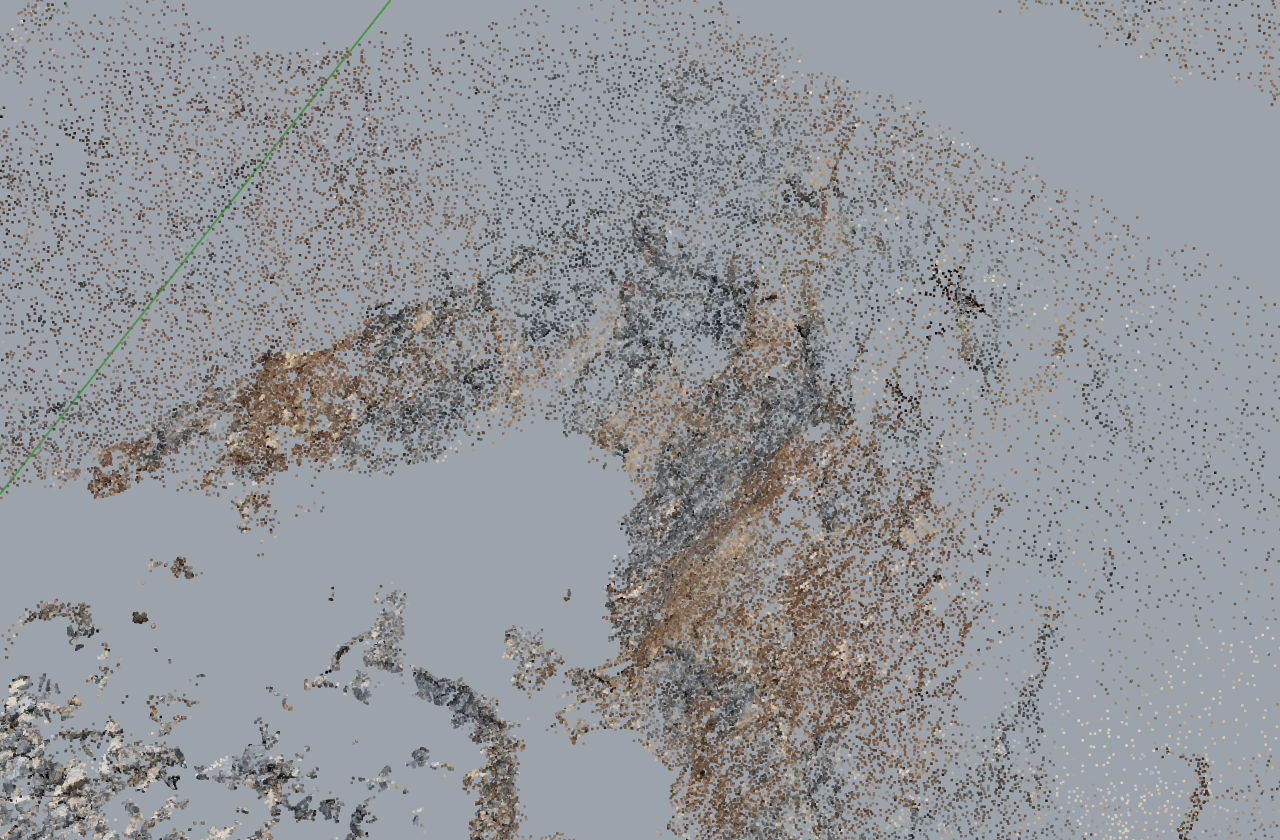
Scan-to-mesh reconstruction works on the subsampled cloud: it reconstructs to a closed surface via the Advancing-Front backend (out-of-process worker), 59,971 verts / 111,973 tris in 3.9 s, with the long spanning triangles being cap artifacts that the cleanup node peels (reconstruction is chapter 10).
Two limitations are documented rather than hidden. LiDAR .laz needs laszip,
not Rhino import: a plain Rhino -Import of ot_GD_TLS_data_UTM.laz produces
zero objects, so .laz/.las must route through LazCloudReader (the
laszip.net path) or convert to E57 for the worker
(examples/07_scan_ingest_full/README.md). GPR .rd3 reads via the Core
reader (986 traces with picks on the Grimsel granite file). The
Import Photo Markers component (GUID F2D07A03-...) completes the
photogrammetry path: it reads markers/GCPs from a Metashape/COLMAP/RealityCapture
export or a plain GCP CSV and feeds them into the Georeference align-by-points
node, so a floating photogrammetry result is positioned and scaled onto a known
base. The repository ingests markers but deliberately does not reconstruct
photogrammetry (ImportPhotoMarkersComponent.cs:12-25).
12.7 Status & what's left¶
.gsfproprietary dead-stop. Any dataset that ships only Geoscanners AKULA.gsfcannot enter the pipeline without a manual GPRSoft or RGPR conversion to SEG-Y (GprFileReader.cs:46-51). This is a deliberate bridge, not a defect, but it blocks.gsf-only sources. Severity: low.- Multi-channel DZT not de-interleaved. A GSSI
.dztwithrh_nchan > 1is read as a single concatenated scan stream; all known test files are single-channel, and de-interleaving is a TODO when a multi-channel granite file appears (GprDztReader.cs:30-33). Severity: medium. - MALA marker positions not applied. Traces from a
.rd3are laid along the +X axis at the header distance interval; companion.cor/.mrkGPS marker positions are parsed but not yet written toGprTrace.X/Y(GprMalaRd3Reader.cs:34-37). The trace geometry is therefore a straight line, not the true survey path, until markers are wired. Severity: medium. - Vector readers do not reproject. Output curves are in source-CRS units; a
file in projected metres (Loviisa
EUREF_FIN_TM35FIN) stays in those units, and GeoJSON carries no CRS at all (ShapefileFractureReader.cs:31,GeoJsonFractureReader.cs:11-19). This is correct (no silent datum error) but pushes reprojection onto the user. Severity: low. - E57 worker is an external dependency.
Load E57 Cloudneeds python + pye57 - numpy on PATH and
frahan_e57_worker.pydeployed beside the.gha; if any is missing the component reports the failure but cannot read the file (E57CloudWorker.cs:167-191,LoadE57CloudComponent.cs:42-48). Severity: medium. - No
.las/.lazcanvas reader in the default install path is validated end-to-end in Rhino. The README marks.lazingest as routed through the harnesslaszip.net.dll; a live in-Rhino validation of the LAS/LAZ component on the 357M-point tile is the remaining truth-criterion step (examples/07_scan_ingest_full/README.md). Severity: low. - Third-party notices owed. NetTopologySuite, laszip.net, and the pye57 worker
dependency chain each owe a
THIRD_PARTY_NOTICES.mdrow before public release (the licensing register,90_originality.md). Severity: medium.
References (this chapter)¶
- Huber, E., Hans, G. (2018). RGPR — an open-source package to process and visualize GPR data. 2018 17th International Conference on Ground Penetrating Radar (GPR), IEEE, pp 1-4. DOI 10.1109/ICGPR.2018.8441658.
- Lucius, J.E., Powers, M.H. (1999). USGS Open-File Report 02-166: GPR data-format documentation (pulseEKKO DT1/HD public-domain spec).
- Isenburg, M. (2013). LASzip: lossless compression of LiDAR data. Photogrammetric Engineering & Remote Sensing 79(2):209-217. DOI 10.14358/PERS.79.2.209.
- Turk, G. (1994). The PLY polygon file format. Stanford University Graphics Laboratory.
- ASTM E2807-11 (2011, reapproved). Standard specification for 3D imaging data exchange, version 1.0 (E57 format).
- ASPRS. LAS specification version 1.4-R15. American Society for Photogrammetry and Remote Sensing.
- SEG Technical Standards Committee. SEG-Y data exchange format, revisions 0/1/2. Society of Exploration Geophysicists.
- NetTopologySuite.IO.Esri. ESRI Shapefile and GeoJSON readers implementing OGC Simple Features. https://github.com/NetTopologySuite.
- Annan, A.P. (2009). Electromagnetic principles of ground penetrating radar. In: Jol, H.M. (ed.) Ground penetrating radar: theory and applications. Elsevier, Amsterdam, pp 3-40. ISBN 9780444533487. (Two-way travel-time depth relation.)
13. Lab, Analysis & Reporting¶
This chapter covers the repository's instrumentation surface: the three
ribbon tabs that do not produce primary stone geometry but inspect, measure,
and report on the subsystems that do. They are Lab (26 components, the
third-largest subcategory), Reports (3 components), and Analysis (3
components). None of these is a new solver. Their contribution is access:
exposing a Core primitive for diagnostics, summarising a solver's output as
typed metrics, or formatting those metrics per audience. The interesting
design questions here are governance questions, not mathematics ones. What
keeps the Lab tab from becoming a junk drawer of dead probes? What stops a
monolith like the heterogeneous-extraction pipeline from becoming an opaque
black box that hides the published primitives it composes? The repository
answers both with explicit rules that this chapter audits against the source.
Two governance rules from the project's working notes bind every component
below. The lab-not-an-island rule requires every Lab node to carry a
[RelatedComponent] attribute pointing at a real production sibling (a 3D
packing, quarry, or mesh component), so a Lab probe is never a dead-end.
The monster-vs-primitive rule requires every monolithic facade (the
HeteroExt pipeline is the canonical case) to be a thin orchestrator over
published Core primitives, with the same engine also exposed standalone, so
both the composed convenience node and its decomposed primitives ship
together. The honesty convention of AGENTS.md §6 governs the whole tab: no
ghost component, every node must produce a real, valid output, and a node
that returns empty is a defect to be flagged, not a feature.
13.1 The Lab subcategory: what it is and what it is not¶
Lab is the reserved subcategory for diagnostic and research-probe
components: native-shim exercisers, single-objective inspectors over a
production solver, and one or two "answer a specific question" bonus
packers. The central allow-list LabConfig documents the design intent
precisely. Lab-gating is a visibility flag only: a Lab-gated component
never has its source, icon, GUID, or .csproj entry deleted, and removing a
GUID from the gate returns the component to its default ribbon (a reversible
operation). The current gate is intentionally empty:
The Lab subcategory itself stays reserved for genuinely miscellaneous / scratchpad / experimental future components that need an enabling configuration to use. None qualify in v1.0. (
Attributes/LabConfig.cs:28-35.)
That comment records a 2026-05-30 reversal: eleven GUIDs were once force-gated
into Lab, then released because they "turned out to be real, named
algorithms / production paths, not miscellaneous" (LabConfig.cs:18-26). The
Lab tab today is therefore populated by components whose own base
constructor declares "Frahan", "Lab", not by runtime gating. There are 26
such components across six source files.
| File | Count | Components (short name) |
|---|---|---|
CgalTestComponents.cs |
8 | MeshCsgCgal, SkeletonCgal, MeshRepairCgal, DecimateCgal, PartitionCgal, SegmentSdfCgal, SegmentAngleCgal, GeodesicVoronoiCgal |
GeogramTestComponents.cs |
8 | DecimateGeogram, RepairGeogram, ObbGeogram, RemeshGeogram, TetGeogram, CvtGeogram, RvdGeogram, FillHolesGeogram |
BlockCutOptInspectorComponents.cs |
5 | BCOPareto, BCORobust, BCOWatershed, VtuOut, BCOMixedPack |
AutoMeshComponents.cs |
3 | RepairAuto (retired), DecimateAuto, ObbAuto |
CoacdTestComponents.cs |
1 | DecomposeCoacd |
DownloadFrahanDataComponent.cs |
1 | GetData |
These group into three roles. Native-shim exercisers (the CGAL, Geogram,
CoACD, and Auto families, 20 of the 26) are Grasshopper surfaces that drive
the out-of-process geometry kernels end-to-end and report which back end
actually ran. Solver inspectors (the five BlockCutOpt components) wrap a
production quarry solver and surface a single axis or a robustness sweep that
the production node does not expose. Distribution helper (GetData) is
the on-demand large-asset fetcher. The taxonomy matters for the originality
call-outs: the exercisers are wrappers over vendored or in-tree kernels, the
inspectors are evolved or clean-room math over a cited baseline, and the
helper is a Frahan-original utility.
13.1.1 The lab-not-an-island rule, audited¶
The rule is verifiable by attribute. Every one of the 26 Lab components
carries at least one [RelatedComponent] pointing at a production sibling.
Sampling the families:
MeshCsgCgalredirects toFrahan > Masonry > Mesh CSGandSlab Cut By Fractures(CgalTestComponents.cs:120-121).DecimateGeogramredirects toFrahan > Mesh > Mesh Repair, with the honest note "no production decimate component yet" (GeogramTestComponents.cs:26).BCOParetoredirects toBlockCutOpt SolveandBlockCutOpt Omni Solve(BlockCutOptInspectorComponents.cs:39-40), the production solvers whose Pareto front it visualises.DecomposeCoacdredirects toMasonry Assembly,Auto Interfaces, andMesh Diagnostics(CoacdTestComponents.cs:29-31).
No Lab node was found without a production cross-reference. The rule holds
across the tab as shipped.
13.1.2 Native-shim exercisers (CGAL / Geogram / CoACD / Auto)¶
These nodes are wrappers, not algorithms. They marshal a Rhino Mesh to the
shared MeshSnapshot interop record, call the managed wrapper over the native
shim, and marshal back, reporting the back end (Geogram, Cgal,
ManagedBsp, or None) and a timing line. The marshalling itself is the only
in-tree work: the conversion welds coincident vertices and drops unreferenced
ones, because Rhino's procedural primitives emit duplicated corner vertices
(24 for a cube instead of 8) and CGAL corefinement then treats every edge as a
boundary and returns hole-ridden output (CgalConvert.ToSnapshot,
CgalTestComponents.cs:29-64). The Auto* family adds one layer: it asks the
MeshOps facade to pick the best available back end (Geogram first, CGAL
fallback) and reports which ran (AutoMeshComponents.cs:55-88).
Originality. The shim exercisers are wrapper-of-native for the call path and clean-room for the marshalling. The cited kernels are: CGAL Polygon Mesh Processing corefinement (
[Algorithm]CgalTestComponents.cs:119), Geogram vertex-clustering decimation (Levy, Geogram v1.9.9, BSD-3,GeogramTestComponents.cs:25), CoACD (Wei et al. 2022, SIGGRAPH,CoacdTestComponents.cs:28), and the CGAL straight skeleton, SDF segmentation, and geodesic-Voronoi probes. Licensing. CGAL is GPLv3 and CoACD vendors CGAL transitively; both are reached only through optional out-of-process shims absent from the default install, with a managed BSP fallback. The GeogramTetGeogramnode wraps Geogram's TetGen path, which is AGPL and on by default in the geogram build, gated behind-DFRAHAN_WITH_TETGENfor an AGPL-free configuration (GeogramTestComponents.cs:547,:738; licensing register flags E3-E6). The Clipper2 and Kazhdan-Poisson permissive paths carry attribution only.
13.1.3 Solver inspectors (the BlockCutOpt Lab five)¶
These are the algorithmically interesting Lab nodes. Each wraps the quarry
block-cutting solver of Chapter 3 and surfaces information the production node
withholds.
Pareto front inspector (BCOPareto, GUID F2D0BC10). The production
BlockCutOpt Omni Solve returns three of four objectives; the inspector runs
BlockCutOptOmniSolver and surfaces all four optima per sub-zone in parallel:
recovery-max, revenue-max, kerf-time-min, and the Jalalian BCSdbBV cost-min
(BlockCutOptInspectorComponents.cs:147-167). The fourth axis is the
sustainable-mining cost objective
cutting-surface area \(S\) over block value \(BV\) (Jalalian et al. 2023): minimise
the sawn surface per unit of recovered value. The inspector exposes the
Front.BestBcsdbBv() extremum that the single-best-recovery production output
hides.
Fisher-robust solver (BCORobust, GUID F2D0BC11). A single
deterministic optimum is fragile: the best cutting direction \(\psi\) depends on
fracture orientations measured with scatter. BCORobust runs the solver \(M\)
times against \(M\) Fisher-perturbed realisations of the same joint sets and
reports the percentile band, not the point estimate
(BlockCutOptInspectorComponents.cs:270-289).
Original framing: the robust optimum is the median direction. Given \(M\) Monte-Carlo samples each returning a recovery \(R_k\) and a best direction \(\psi_k\), the deterministic best \(\psi^\star\) over the unperturbed mean orientations can sit on a knife-edge. The robust score is the lower percentile
so the reported direction is the one that survives orientation noise rather
than the one that maximises a single noiseless realisation (Azarafza et al.
2016 Fisher-scatter reading; synthesis axis I8). The component returns
\(R_{p10}/R_{p50}/R_{p90}\), the mean, the standard deviation, and the per-sample
arrays for the caller's own histogram
(BlockCutOptInspectorComponents.cs:219-228). The base seed makes the sweep
reproducible (:216).
Density-watershed zones (BCOWatershed, GUID F2D0BC12). Replaces the
uniform \((m_x,m_y)\) sub-division with an adaptive partition whose zone
boundaries snap to high-density fracture ridges, so the unavoidable
boundary-cut penalty lands on already-broken rock
(BlockCutOptInspectorComponents.cs:340-381). It is the GH front end to the
in-tree DensityWatershedPartition (synthesis I5).
VTU export (VtuOut, GUID F2D0BC13). Runs the solver, regenerates the
winning tilted cutting grid, classifies each cell against the triangle-AABB
BVH as intersected or clear, and writes a ParaView .vtu with two cell sets,
matching the BlockCutOpt 2020 paper's figure convention
(BlockCutOptInspectorComponents.cs:463-499). A default-false Write gate
keeps the file I/O off until requested.
Originality.
BCOParetois clean-room over the cited Jalalian 2023 BCSdbBV axis ([Algorithm]BlockCutOptInspectorComponents.cs:38); it adds no algorithm, only the fourth-axis surfacing.BCORobustis clean-room Monte-Carlo robustness sampling over the cited Azarafza 2016 Fisher reading (:175).BCOWatershedfronts a clean-room Frahan-original partition (:298, "Core DensityWatershedPartition.cs verified-original").VtuOutis a facade-over-primitives export node composing the solver, the cutting grid, and the BVH. All four are diagnostic surfaces over the Chapter 3 production solvers, each carrying the[RelatedComponent]redirect required by the lab-not-an-island rule.
13.1.4 The bonus mixed-size packer and the monster-vs-primitive balance¶
BCOMixedPack (GUID F2D0BC17) is the one Lab node that is not a probe but
a standalone packer. It answers a direct question the project owner asked:
"can we pack multiple sizes instead of one size for the entire quarry?". It
exposes the 2D Deepest-Left-Bottom-Fill packer DlbfMixedSizePacker
directly: a multi-size catalogue with per-size revenue, pieces sorted by
revenue-per-area, placed at the deepest-then-leftmost free grid cell, with
optional forbidden boxes encoding fracture-intersected regions
(BlockCutOptInspectorComponents.cs:559-620; engine
DlbfMixedSizePacker.cs:8-25). Pieces sort by
the revenue-per-area density (DlbfMixedSizePacker.cs:46), and the placement
rule scans the discrete grid for the deepest-left-bottom feasible cell
(Chehrazad, Roose, Wauters 2025).
This is the load-bearing example of the monster-vs-primitive rule. The
same DLBF engine is the core of the monolithic HeteroExt pipeline
(FrahanHeterogeneousExtractionComponent, GUID F2D0BC19, on the Quarry
tab), a four-stage facade that runs BlockCutOpt to find fracture-clean
regions, marks intersected cells forbidden, runs 3D DLBF mixed-size packing,
and optionally places monuments
(BlockCutOptHeterogeneousComponents.cs:179-191). The monolith's
[Algorithm] names itself "Frahan-original" but immediately declares that it
"Composes Elkarmoty 2020 (BlockCutOpt) and Chehrazad 2025 (DLBF), both
interpreted and reimplemented in managed code; the composition and the
heterogeneity model are the contribution"
(BlockCutOptHeterogeneousComponents.cs:169). Crucially the monolith carries
explicit [RelatedComponent] back-pointers to the standalone primitives it
composes: to Frahan > Lab > Frahan Mixed-Size Block Pack (the 2D F2D0BC17)
and to Frahan > Quarry > Frahan Mixed-Size Block Pack 3D (the 3D F2D0BC18),
each annotated "the same engine this facade composes"
(:170-173). Both the composed convenience and the decomposed primitive ship,
the seams are exposed, and the engine is never a black box. This is the rule
satisfied, with the Lab tab holding the 2D primitive seam.
Originality.
BCOMixedPackis clean-room over the cited DLBF (Chehrazad, Roose, Wauters 2025, DOI 10.1080/00207543.2025.2478434,BlockCutOptInspectorComponents.cs:509).HeteroExtis facade-over-primitives: a Frahan-original composition with no new algorithm, its two cited sub-algorithms each exposed standalone (BlockCutOptHeterogeneousComponents.cs:169-173). The pairing is the monster-vs-primitive rule made executable.
13.1.5 The distribution helper¶
GetData (GUID F2D05A08) fetches optional large assets (the Kintsugi
kintsugi.bin weights plus the Torch/CUDA runtime, or the examples bundle)
from a release manifest into the deploy folder, SHA-256-verifying each file,
on a background thread so the canvas stays responsive
(DownloadFrahanDataComponent.cs:36-58). It keeps the install lean by moving
the non-redistributable and the heavy off the .gha.
Originality. original-research is overstated for a utility; this is a Frahan-original distribution helper (
[Algorithm]DownloadFrahanDataComponent.cs:36-38), an engineering utility, not a research contribution. Its licensing relevance is real: it is the mechanism by which the GPL-3.0 / non-commercial Kintsugi weights stay out of the default permissive install until the user explicitly fetches them.
13.2 The Reports tab: typed metrics from solver output¶
The Reports tab holds three components, each a thin Grasshopper marshaller
over a Rhino-free Core report type. The math is elementary; the contribution
is a single canonical metrics surface so every solver reports the same way.
13.2.1 Packing metrics¶
PackRpt (GUID AB12C004) consumes an opaque PackResult from any 3D pack
solver and surfaces Frahan.Core.PackingMetrics. The Core computes placement
and failure counts, the failure ratio, packed and container volumes, the fill
ratio, the average placement score, item-volume statistics, and a per-reason
failure breakdown (PackingMetrics.cs:72-133). The two headline ratios are
and the per-reason histogram is built by counting Failure.Reason strings
(PackingMetrics.cs:112-118). The component orders the failure reasons by
descending count and emits a single-line summary
(PackingReportComponent.cs:101-106). The Core is static, side-effect-free,
and allocates only the returned report dictionary
(PackingMetrics.cs:64-67).
13.2.2 Packing-plan report¶
PackPlanRpt (GUID AB12C008) aggregates three pieces into one composite
PackingPlanReport: the PackingMetricsReport, a residual-void list, and the
per-fragment-per-edge match scores from the edge-matcher
(PackingPlanReportComponent.cs:164-182; builder PackingPlanReport.cs:51-91).
The two scalars it derives are the total residual-void area (a sum of
per-void approximate areas) and the mean best-edge-match score (a flatten-then-
average over the nested per-fragment score lists):
The pieces are decoupled, so a caller can pass any subset and null for the
rest (PackingPlanReport.cs:46-48). The component accepts edge scores three
ways: a nested opaque list, a flat opaque list, or a Grasshopper
DataTree<Number> with one branch per fragment, the tree taking precedence
when both are wired (PackingPlanReportComponent.cs:114-162). That tree path
is the natural Grasshopper UX; the opaque path stays for code that already
produces nested lists.
13.2.3 Audience report¶
Report (GUID AB12C010) is the single report/export terminal driven by an
Audience enum (engineer / artist / geologist). It consumes the typed
FrahanReport records the kept solvers emit (Packing, MeshDiagnostics,
FabricationPrep, BlockCutOpt, ChartFlatness) plus optional pipe-delimited
section rows, then orders, routes, flags, and formats per audience, applying
the spec's audience rules: the engineer release is refused without a
declared CRS/datum, the artist flags grain/vein UNKNOWN, the geologist flags
rock-mass needing a worksheet (AudienceReportComponent.cs:27-46). Output is
Markdown plus CSV; with Run and a path it writes the files
(AudienceReportComponent.cs:147-169). The composition logic is Rhino-free and
unit-tested in Frahan.Core.Reports.AudienceReportComposer; the component is a
thin marshaller (:24-26). The CRS refusal is the only "gate" in the tab: a
correctness guard against shipping an unreferenced mining plan
(Tolerance = "Engineer release refused without a declared CRS/datum",
:31).
Originality. All three report components are facade-over-primitives: Frahan-original report generators over the cited spec sections (spec 5 §5, spec 7 §5), composing pure-data Core DTOs. The
[DesignApplication]precedents name them "Frahan-original packing-report generator" (PackingReportComponent.cs:25), "Frahan-original packing-plan report" (PackingPlanReportComponent.cs:24), and the "SAMPLE_GH_SPEC.md three-audience report terminal" (AudienceReportComponent.cs:30). No new algorithm; the contribution is one canonical, audience-aware metrics surface.
A note on scope: the ChartFlatnessReport named in this subsystem lives in
Core under Frahan.Surface (ChartFlatnessReport.cs), but its Grasshopper
front end ChartFlat (GUID AB12C006) is filed on the Surface Packing
tab, not Reports (ChartFlatnessReportComponent.cs:32). Its math is a
per-face area-ratio distortion test using \(\max(r, 1/r)\) so \(0.5\times\) and
\(2\times\) count as equally distorted (ChartFlatnessReport.cs:90-101); it is
clean-room Frahan-original, not the BFF algorithm
(ChartFlatnessReportComponent.cs:23-24). It is reported here because it is
one of the five FrahanReport record types the audience terminal consumes,
and the roadmap proposes driving an adaptive surface re-cut from it.
13.3 The Analysis tab: edge-matching diagnostics¶
The Analysis tab holds three components, all moved there on 2026-05-05 from
2D Packing to make their diagnostic role explicit. Each was once wired into
the irregular-sheet packer; the unified solver now folds boundary scoring in
internally, so these standalone nodes survive only to inspect the index the
solver builds, debug affinity scores, and export for ad-hoc analysis. None
needs to be wired into the solver any more
(BoundaryRailIndexComponent.cs:19-25).
RailIdx(GUIDAB12C001) builds aBoundaryRailIndexfrom boundary curves: each curve is sliding-window-sampled into (length, tangent angle, curvature) buckets and stored as aBoundaryIntervalInfo(BoundaryRailIndexComponent.cs:38-52).FragDesc(GUIDAB12C007) converts closed planar curves intoFragmentDescriptors with per-edgeEdgeDescriptors and surfaces area, perimeter, aspect ratio, and edge counts (FragmentDescriptorsComponent.cs:34-47).FragMatch(GUIDAB12C003) matches each fragment edge against a populated index and returns ranked affinity scores as oneDataTree<Number>branch per fragment (FragmentEdgeMatchComponent.cs:38-51).
The three compose a pipeline: RailIdx builds the index, FragMatch queries
it with FragDesc descriptors. The bucketing is arc-length affinity over a
turning-function representation (Arkin et al. 1991 is the turning-function
shape-metric precedent).
Originality. All three are clean-room Frahan-original diagnostics: the geometric descriptors are textbook quantities but the descriptor schema and the affinity-bucket index are Frahan-original (
[Algorithm]notes "geometric descriptors are textbook quantities but the descriptor schema is Frahan-original",FragmentDescriptorsComponent.cs:29-31; "arc-length affinity bucketing, not a published algorithm",BoundaryRailIndexComponent.cs:33-35). They carry no production[RelatedComponent]redirect because they are notLab-gated; their production home is the unifiedFrahan Sheet Pack, which absorbed their function (FragmentEdgeMatchComponent.cs:20-24).
13.4 Status & what's left¶
- Retired Lab ghost (
RepairAuto).AutoMeshRepairComponent(GUIDF2D000D0) is markedObsoleteandExposure=hidden, superseded bySanitize Mesh (Backend=Auto)which runs the sameMeshOps.Repairplus a CGAL-Ready verdict; the GUID is preserved so existing canvases keep loading (AutoMeshComponents.cs:34-40). This is the hide-not-delete pattern done correctly, not a defect. Low. - Lab decimate has no production sibling.
DecimateGeogramandDecimateCgalredirect toMesh Repairbecause there is no production decimate component yet (GeogramTestComponents.cs:26). The lab-not-an-island rule is satisfied by the redirect, but the honest implication is a missing production node: aMesh Decimateshould be promoted out ofLab. Medium. - AGPL exposure via
TetGeogram. The tetrahedralise probe wraps Geogram's TetGen path, which is AGPL and on by default in the geogram build; an AGPL-free configuration requires-DFRAHAN_WITH_TETGEN=OFF, which disables volumetric Voronoi blocks (GeogramTestComponents.cs:547,:738; register flag E6). The native shims are absent from the default install, so the default path is clean, but a packager who turns on the shims must honour the flag. High. - Greedy Trencadís ghost (cross-subsystem). The named-but-empty
Frahan Trencadís Packbox (GUIDF2D00002, 2D Nesting tab) returns empty output on the primary ribbon, anAGENTS.md§6 violation; it is not aLabnode, but it is the canonical ghost the Lab governance rules exist to prevent. The fix is to implement the greedy pack or move the box off the primary ribbon and route users to Catalog / Pipeline (roadmap item 5,91_roadmap.md:42,:88). Medium. ChartFlatnessReportis under-used. The Core flatness classifier feeds only the audience terminal today. The roadmap proposes driving an adaptive per-face surface re-cut from it (91_roadmap.md:48), which would make it a control input rather than a report-only leaf. Low.- Reports tab has no rendered figure. The
ReportsandAnalysistabs ship no dedicated example folder; the embedded figure borrows example 09 (the uncertainty-safe yield), the production output the Lab BlockCutOpt inspectors instrument. Low (documentation gap, not a code gap).
References (this chapter)¶
- Chehrazad, R., Roose, D., Wauters, T. (2025). A fast and scalable deepest-left-bottom-fill algorithm for the 3D bin packing problem. International Journal of Production Research 63:6606-6629. DOI 10.1080/00207543.2025.2478434.
- Elkarmoty, M., Bondua, S., Bruno, R. (2020). Mechanized in-situ determination of joint-related and yield-related rock-mass parameters during dimension stone block extraction. Resources Policy 68:101761. DOI 10.1016/j.resourpol.2020.101761.
- Jalalian, M.H., Bagherpour, R., Khoshouei, M. (2023). Environmentally sustainable mining in quarries to reduce waste production and loss of resources using the developed optimization algorithm (BCSdbBV). Scientific Reports 13:22183. DOI 10.1038/s41598-023-49633-w.
- Azarafza, M. et al. (2016). Granite block-cut analysis with Fisher- distribution joint-orientation scatter.
- Wei, J., Liu, M., Wang, J. et al. (2022). Approximate convex decomposition for 3D meshes with collision-aware concavity and tree search (CoACD). ACM Transactions on Graphics (SIGGRAPH 2022) 41(4):42. DOI 10.1145/3528223.3530103.
- Levy, B. (INRIA/ALICE). Geogram: a programming library of geometric algorithms (v1.9.9). BSD-3.
- The CGAL Project (2023). CGAL user and reference manual. CGAL Editorial Board. GPLv3 / commercial.
- Lloyd, S.P. (1982). Least squares quantization in PCM. IEEE Transactions on Information Theory 28(2):129-137. DOI 10.1109/TIT.1982.1056489.
- Arkin, E.M., Chew, L.P., Huttenlocher, D.P., Kedem, K., Mitchell, J.S.B. (1991). An efficiently computable metric for comparing polygonal shapes. IEEE Transactions on Pattern Analysis and Machine Intelligence 13(3):209-216. DOI 10.1109/34.75509.
- Sawhney, R., Crane, K. (2017). Boundary first flattening. ACM Transactions on Graphics 36(4):109. DOI 10.1145/3072959.3056432.
14. Workflow Architecture & Data-Flow Connections¶
This chapter is cross-cutting. The preceding chapters classify individual
algorithm families; this one maps how they connect into end-to-end
workflows. The repository is not a bag of components. It is one data-flow
spine, ingest to fabricate, with a small number of subsystem branches that
re-enter that spine at well-defined seams. The 28 worked examples in
examples/ are the evidence: each is a Grasshopper definition that wires a
slice of the spine. Reading the 24 example READMEs and the four
README-less canvases together recovers the architecture as built, not as
imagined.
Three structural facts govern the whole repository and recur in every section below.
- Rhino-free Core. The algorithms live in
Frahan.StonePack.Core(net48, no RhinoCommon reference). The Grasshopper layerFrahan.StonePack.GHis a thin facade: it marshals canvas geometry to Core types, calls one engine, and marshals back. This is why headless harness numbers exist at all, and why AGENTS.md §1 can distinguish "measured" (Core, harness) from "validated" (seen in Rhino). - Native bridges behind a C ABI. Heavy geometry (booleans, remesh,
reconstruction, convex decomposition, exact NFP) is done in native DLLs
wrapped by P/Invoke shims (
native/). The managed side owns only the marshalling. AGENTS.md §3 routes the crash-prone ones out of process. - Facade-over-primitives. The big single-box components (HeteroExt, the Unified sheet filler, the hole-aware nester) compose published Core primitives. They add convenience, not new mathematics, and the composed-equivalent canvas exists alongside them.
14.1 The data-flow spine¶
Every workflow is a path through one acyclic spine: a site or a form is ingested, reconstructed to clean geometry, segmented into regions, then packed or cut into fabricable pieces, stabilised (settling for piles, a limit-state certificate for assemblies), and emitted as a cut plan or an install order.
flowchart LR
  subgraph INGEST
    A1[Read LAS Cloud<br/>.las/.laz laszip]
    A2[Load E57 / PLY Cloud<br/>out-of-proc worker]
    A3[GPR File Loader<br/>.rd3/.DT GprFileReader]
    A4[Vector Fractures Loader<br/>.shp NetTopologySuite]
  end
  subgraph RECONSTRUCT
    B1[Estimate Cloud Normals]
    B2[Scan Reconstruct<br/>Poisson/AdvFront/Alpha]
    B3[Sanitize / Remesh<br/>geogram FillHoles+Remesh]
  end
  subgraph SEGMENT
    C1[Mesh Segmentation by Angle<br/>CGAL]
    C2[GPR Fracture Extract<br/>Stolt f-k + Hilbert]
    C3[Bench From Mesh / offset]
    C4[Statue grid x CGAL boolean]
  end
  subgraph PACK_CUT
    D1[Block Pack Tree<br/>DLBF guillotine]
    D2[Fracture Block Pack<br/>keep-out aware]
    D3[Sheet Nest Hole-Aware<br/>exact NFP-BLF]
    D4[Trencadis Catalog Pack<br/>CVD-Lloyd + Hungarian]
    D5[Ashlar Pack / Polygonal Seq]
    D6[BlockCutOpt / guillotine seq]
  end
  subgraph STABILISE
    E1[Rubble Wall Settle<br/>PCA + dimple drop]
    E2[Settle 3D Physics<br/>Bullet]
    E3[Masonry Stability RBE<br/>Kao 2022 CRA]
  end
  subgraph FABRICATE
    F1[Guillotine cut planes]
    F2[Planes to Robot / KUKA PRC]
    F3[Wire-saw toolpath / G-code]
    F4[IFC terminal xBIM]
  end
  A1 --> B1 --> B2 --> B3 --> C3
  A2 --> B2
  A3 --> C2 --> D2
  A4 --> C2
  B3 --> C1 --> D4
  B3 --> C4 --> D1
  C3 --> D1
  C2 --> D2 --> D6 --> F1
  D1 --> E2
  D3 --> F3
  D4 --> F2
  D5 --> E3 --> F4
  E1 --> E3
  D1 --> F1 --> F2
  F1 --> F3
The spine has four ingest mouths (point cloud, GPR radargram, vector shapefile, and an in-canvas designed form), one reconstruction lane, three segmentation modes (dihedral surfaces, GPR fracture surfaces, grid-boolean blocks), six pack-or-cut engines, three stabilisers, and four fabrication terminals. Each example below is one route through this graph.
14.2 Per-example pipeline graphs¶
Each line is the component chain the example wires, read left to right.
Bracketed names are Grasshopper components; arrows are canvas connections.
Folders without a README ship a .gh + .3dm only; their chain is read
from the canvas and the figure catalogue.
| # | Example | Pipeline chain (component graph) |
|---|---|---|
| 01 | Quarry to wall | Scan/Block source -> Block Pack -> Masonry layout -> Wall (full spine, definition only) |
| 02 | Masonry assembly | Blocks -> Polygonal Masonry Sequence -> colour-by-install-order preview |
| 03 | GPR fracture (granite) | GPR File Loader (.rd3) -> RadargramProcessor (f-k migrate) -> GPR Fracture Extract -> GPR Fracture Surfaces 3D -> report |
| 03b | Quarry to slabs | Block source -> Fracture Block Pack -> Slab Cut By Fractures -> slabs (canvas only) |
| 04 | Scan to bench | Read LAS Cloud (.laz) -> Estimate Cloud Normals -> Scan Reconstruct (Poisson/Geogram) -> Bench From Mesh + offset -> packable volume |
| 05 | Artist pointing machine | Scan mesh (decimated) -> Carving Stages -> staged meshes + pointing coords |
| 07 | Scan ingest (full) | Load E57 / .ply / .laz -> outlier-clean + crop -> Scan Reconstruct (Advancing-Front, out-of-proc) -> Clean Scan Mesh -> hand-off |
| 08 | GPR marble + layout | GPR File Loader (.DT) -> GPR Fracture Extract -> 3 dipping beds -> net + W*volume block pack -> oblique guillotine sequence |
| 09 | Uncertainty-safe yield | GPR Fracture Surfaces 3D -> Fracture Clearance = sigma -> Fracture Block Pack -> per-zone yield |
| 10 | 2D nest | part curves + sheet + holes -> Sheet Pack (Unified) V506 / Freeform Sheet Nest (Exact NFP) -> packed curves + util_stock |
| 11 | 3D block pack | element boxes + container -> Block Pack (Tree) / DLBF -> placed boxes (12/12) + report |
| 12 | Trencadis mosaic | shard catalog + sheet -> Trencadis Catalog Pack (CVD-Lloyd + Hungarian) -> placed pieces + grout |
| 13 | Surface mapping | twisted mesh -> Mesh Segmentation by Angle (CGAL) -> 6 regions -> Surface Chart (BFF) -> Pack On Surface -> 176-shard mosaic |
| 14 | Kintsugi reassembly | Load BB Sample (.bin) -> Frahan Kintsugi (Port mode) -> assembled fragments + verifier score |
| 15 | Statue to blocks | Read PLY -> Geogram FillHoles/Remesh/FillHoles -> 0.5 m grid x CGAL intersect -> 113 real-face blocks -> Branch A gangsaw / Branch B rubble match |
| 16 | Rubble masonry | 40 ETH1100 stones -> Rubble Wall Settle (PCA + dimple drop) -> staggered wall, 36/40 stable |
| 17 | Ashlar masonry | 60-block inventory -> Ashlar Pack (running bond) -> Pack Preview -> coursed wall (45 placed) |
| 18 | Pack + settle (Bullet) | 12 stones + container -> Settle 3D (Physics, Bullet) -> dense non-interpenetrating pile |
| 19 | Rubble evolved fit | blocks + stones -> Rubble Evolved Fit (24 seeds + (1+8)-ES) -> 10/10 enclosed, one block per stone |
| 20 | Rubble multi-bin | blocks + stones -> Rubble Multi-Bin Pack (voxel-occupancy FFD) -> 17/20 across 6 bins |
| 21 | Stereotomy arch | Arch Voussoirs (D5F10012) -> cells -> evolve-match to ETH stone -> CgalMeshBoolean.Intersection -> 11/11 carved voussoirs |
| 22 | Pendentive vault | Pendentive Vault Voussoirs (D5F10013) -> 36 cells -> evolve-match -> CGAL trim -> 36/36 carved |
| 23 | Quarry to slab | fracture-prone block -> Fracture Block Pack (voxel-dlbf-multi) -> intact blocks -> gangsaw slab cut |
| 24 | Guillotine sequence | packed block -> rip(perp-X) -> cross(perp-Y) -> cross(perp-Z) -> 19 saw planes as meshes |
| 25 | Marble gangsaw cost | fractured bench -> Fracture Block Pack -> net + W*volume sweep (Pareto) -> balanced -> guillotine planes |
| 26 | Loviisa surface fractures | Vector Fractures Loader (.shp, F2D00BEC) -> FractureTraceCollection -> strike map (708 traces) |
| 27 | Polygonal masonry | chains/cells + wall -> Polygonal Masonry Sequence (B4E07A3C) / ...3D (C5F18B4D) -> install order DAG -> colour-by-order |
| 28 | Hole nest | parts + sheet + holes -> Sheet Nest (Hole-Aware) D5F10019 / ContactNfpHoleNester -> nested around holes (canvas only) |
The table makes the spine visible as routes. The geologist spine is 03 -> 08 -> 09 (GPR to uncertainty-safe yield). The engineer spine is 04 -> 11 -> 23 (scan to bench to slab). The artist spine is 05 -> 15 (carving and statue decomposition). The masonry spine is 16/17 -> 27 -> 02 (settle or course, then order, then assemble). Examples 21/22 are the top-down stereotomy bridge, and 13 is the surface-cladding bridge.
14.3 Architectural seams¶
Core vs GH facade¶
The deciding seam is the assembly boundary. Frahan.StonePack.Core
references no RhinoCommon; the engines ContactNfpHoleNester
(src/Frahan.StonePack.Core/Packing/TwoD/ContactNfpHoleNester.cs),
BlockCutOptSolver, Dlbf3dMixedSizePacker, RubbleWallSettle, and
EquilibriumMatrixBuilder are all pure. The GH component is the facade.
For example, BlockPackTreeComponent
(src/Frahan.StonePack.GH/Packing/BlockPackTreeComponent.cs:37, GUID
C2D3E4F5-3001-4F5E-A6B7-C8D9E0F12345) marshals canvas boxes to the
Core packer and back; the [Algorithm] attribute at line 30 cites the
engine, not the wrapper. This is the single most important structural
choice in the repository: it makes the Core independently testable and
keeps the truth criterion honest.
Native bridges¶
Three classes of native bridge cross the managed boundary, all behind a C
ABI (native/README.md is the authority).
frahan_cgal.dll(cgal_shim) wraps CGAL Polygon Mesh Processing: corefinement booleans (used in example 15 grid-intersect and 21/22 voussoir trim), decimation, OBB, straight skeleton, SDF/angle segmentation (example 13), alpha shape, advancing front, Poisson. The CGAL packages used are GPL in that distribution.frahan_geogram.dll(geogram_shim) wraps Bruno Levy's Geogram: remesh, hole-fill, voxel downsample, CVT/Lloyd, and the KazhdanGEO::PoissonReconstructionthat Geogram bundles (example 04/15). Geogram core is BSD-3; bundled PoissonRecon is MIT.nfp_kernel.dllwraps Clipper2 (BSL-1.0, no copyleft) for the batched Minkowski-sum NFP lane thatContactNfpHoleNestercalls (examples 10, 28).frahan_coacd.dllwraps CoACD (MIT, SIGGRAPH 2022) for the convex decomposition in example 15 Branch C and the Bullet settle.
The GH wrappers over these (Scan Reconstruct, Mesh Remesh/Decimate, the
CGAL cut/test components, the CoACD test) carry no managed algorithm; they
marshal to the shim. Crash-prone in-process booleans are routed through
OutOfProcessReconstructor + recon_worker (example 07), per AGENTS.md
§3.
Facade-over-primitives pattern¶
The pattern is explicit in source. FrahanHeterogeneousExtractionComponent
(src/Frahan.StonePack.GH/BlockCutOptHeterogeneousComponents.cs:179)
composes BlockCutOptSolver + Dlbf3dMixedSizePacker + the monument
packer; its [Algorithm] note at line 169 reads "Composes Elkarmoty 2020
(BlockCutOpt) and Chehrazad 2025 (DLBF), both interpreted and reimplemented
in managed code for this plugin; the composition and the heterogeneity
model are the contribution." That is the canonical facade: every internal
step resolves to an in-repo primitive that also ships standalone. The
Unified sheet filler dispatches V506 and the obsolete V1/V2/V3 wrappers;
Sheet Nest (Hole-Aware) D5F10019 is the facade over
ContactNfpHoleNester; Pack On Surface
(src/Frahan.StonePack.GH/SurfacePacking/PackOnSurfaceComponent.cs:41-42)
composes the exact NFP-BLF placement on a BFF chart with a classical
triangle barycentric lift back to 3D (attributed to the mean-value-coordinate
family, after Floater 2003; the shipped lift is plain barycentric, not MVC).
Top-down vs bottom-up design flows¶
The repository tags every workflow by design direction (the
[DesignApplication(..., DesignFlow.TopDown|BottomUp)] attribute, e.g.
GprFractureExtractComponent.cs:46). The two flows are first-class.
- Top-down (form-first). A designed form drives the search for stone. Examples 21/22 generate voussoir cells, then find and trim rubble to fit them. Example 15 takes a sculpted bunny and cuts it into a brick grid. Example 17 fills a wall envelope with dressed ashlar. The form is imposed; the stone is negotiated to it.
- Bottom-up (material-first). Found stone drives the form. Example 16 settles real ETH1100 scans into whatever staggered wall emerges. Example 12/13 lay offcut shards into a Trencadis mosaic. The form is the residue of the material.
The same Core engines serve both: Rubble Evolved Fit (example 19) is the
substrate for the top-down voussoir match (21) and the bottom-up rubble
lot match (15 Branch B).
14.4 Cross-subsystem couplings¶
The architectural interest is in the seams where one subsystem's output is another's typed input. Four couplings carry the workflow weight.
GPR defect -> defect-aware nesting¶
The GPR fracture chain emits 3D fracture surfaces; the packers consume them
as keep-out geometry. GprFractureExtractComponent
(src/Frahan.StonePack.GH/Quarry/GprFractureExtractComponent.cs:43, GUID
A7E0B0F1-...) runs Stolt f-k migration and Hilbert energy; its surfaces
flow into FractureBlockPackComponent
(...Quarry/FractureBlockPackComponent.cs:37, GUID
A7E0B0F3-0C0F-4A16-9E3D-0FACE0FACE04) which packs blocks only in intact
rock. Example 09 closes the loop by wiring the GPR position uncertainty
\(\sigma\) as the inward clearance, so no block sits within the measured
error of a fracture. The 2D analogue is the same idea one dimension down:
a vein or defect becomes a sheet hole, and ContactNfpHoleNester
(example 28) nests parts around it. The coupling is one concept, defect as
keep-out, expressed as a 3D surface margin and a 2D hole.
The packed-yield objective itself is a swept scalar. Examples 08 and 25 both maximise
where \(W\) is a volume credit in dollars per cubic metre. Sweeping \(W\) from \(0\) to \(\infty\) walks the Pareto front from pure profit to pure throughput. At \(W=0\) the loss-making block (negative net) is never placed; as \(W \to \infty\) every cell fills. This single knob is what makes the cost/volume/balanced triptych in both examples one workflow, not three.
Statue -> blocks -> CRA¶
Example 15 decomposes a statue into real-face blocks by intersecting a \(0.5\,\text{m}\) grid with the closed solid. The recovered-volume identity is the correctness certificate:
a complete partition (statue \(5.4009\,\text{m}^3\) = sum of blocks). The blocks then flow two ways: Branch A packs them for a gangsaw, Branch B matches each to a rubble stone. Where those blocks become a built wall (example 27 install order, then assembly), the assembly is handed to the limit-state check below. The chain statue -> blocks -> order -> stability is the full top-down fabrication route.
H-model coupling: RBE accepts / CRA rejects¶
The masonry stability subsystem is a coupled two-stage certificate, and
the coupling is a regression test, not just a workflow. The Rigid-Block
Equilibrium (RBE) stage solves a convex QP for a statically admissible
contact force field. Build the equilibrium matrix \(\mathbf{A}_{eq}\)
(EquilibriumMatrixBuilder.Build), the friction cone
\(\mathbf{A}_{fr}\) (FrictionConeBuilder.Build), and solve
The \(f_n \ge 0\) constraint (no tension at a joint) is the sign that the
audit flagged. The shipped path now calls
RbeQpFormulation.BuildPhysicsCorrected
(src/Frahan.StonePack.GH/Masonry/MasonryStabilityRbeComponent.cs:305),
which flips the sign so \(f_n \ge 0\) means compression, not the inverted
convention of the older Build. RBE feasibility is necessary but not
sufficient: it allows a force field that no realisable rigid motion would
sustain. The CRA (Coupled Rigid-Block Analysis) stage adds the kinematic
side, an alternating-convex soundness certificate that can reject an
assembly RBE accepts. The H-model counterexample, an assembly where RBE
reports feasible and CRA reports unstable, is kept as a regression test:
it is the proof that the two stages are not redundant. The component cites
Kao et al. 2022 at
MasonryStabilityRbeComponent.cs:69 (GUID
F6BAC3D4-4E5F-4071-BC3D-5E6F7A8B9CAD).
Vector + GPR -> shared fracture model¶
Examples 26 (shapefile traces) and 08 (GPR depth) both produce a fracture
model the packers consume. The shapefile gives surface trace strike and
spacing in plan; GPR gives depth. VectorFracturesLoaderComponent
(src/Frahan.StonePack.GH/VectorFracturesLoaderComponent.cs:53, GUID
F2D00BEC-2026-4522-B0B0-1ABE15A0DEAD) returns a FractureTraceCollection
that feeds Slab Cut By Fractures and the fracture-aware packers, the same
sink the GPR surfaces reach. Two ingest mouths, one defect model, one set
of packers.
14.5 Originality call-outs (workflow components)¶
The classification is per the seven-class framework. Evidence is
file:line, the [Algorithm] attribute, or the native shim entry.
- ContactNfpHoleNester / Sheet Nest (Hole-Aware) D5F10019 —
clean-room, with an evolved-fork increment. The BLF and Minkowski-sum NFP
math is cited (Burke et al. 2006; Bennell and Oliveira 2009) at
TwoD/HoleNestComponent.cs:25-34; the Int64 Minkowski lane runs in the vendored Clipper2nfp_kernel. The contact-adaptive rotation set and the part-in-part-hole inner-fit polygon are the increment over plain BLF. - Block Pack (Tree) / DLBF — clean-room from Kim 2025
(
Packing/BlockPackTreeComponent.cs:30, Doi 10.3390/computation13090211), with three Frahan extensions (deterministic seed, saw kerf, per-container forbidden boxes) noted in the README, closing Kim 8.2. - HeteroExt (FrahanHeterogeneousExtraction) —
facade-over-primitives. Composes
BlockCutOptSolver+Dlbf3dMixedSizePacker+ monument packer (BlockCutOptHeterogeneousComponents.cs:169-179). - Masonry Stability (RBE) + CRA — RBE clean-room from Kao et al. (2022) / Whiting
(
MasonryStabilityRbeComponent.cs:69-71, Kao et al. 2022 cited); the CRA alternating-convex certificate is the A-candidate (Kao 2022 solves a nonconvex NLP via IPOPT; ours is a managed soundness certificate). - Polygonal Masonry Sequence (B4E07A3C) + 3D (C5F18B4D) — clean-room
from Kim 2024 (
PolygonalMasonrySequenceComponent.cs:34, DETC2024-142563): Kahn toposort + reversed depth search on the install DAG. - GPR Fracture Extract (A7E0B0F1) — clean-room (tier B). Stolt 1978
f-k migration, Taner 1979 Hilbert attributes, USGS continuity, all cited
at
Quarry/GprFractureExtractComponent.cs:43-46. - Rubble Wall Settle (6514A1BB) — clean-room, Frahan-original settle
with Heyman 1966 COM-over-support stability
(
Masonry/RubbleWallSettleComponent.cs:35-36). - Trencadis Catalog Pack (F2D00007) — clean-room: CVD-Lloyd partition
(Lloyd 1982) + Hungarian assignment (Kuhn 1955)
(
Pack2DTrencadisCatalogComponent.cs:37-38); the slab-partitioned catalog placement is the Frahan extension. - Arch Voussoirs (D5F10012) / Pendentive Vault Voussoirs (D5F10013) —
clean-room from Frezier/Monge stereotomy
(
Voussoir/ArchVoussoirsComponent.cs:31-34); radial bed-joint cells. - Frahan Kintsugi Port — direct-port of PuzzleFusion++ (Wang, Chen,
Furukawa, ICLR 2025, arXiv:2406.00259), parity-verified on Breaking Bad
(
src/Frahan.Kintsugi.Port/README.md:3-4). LICENCE-CRITICAL: GPL-3.0 (Frahan.Kintsugi.Port/LICENSE.txt); the geometric path (Frahan.EdgeMatching.Core, Port mode off) carries no GPL. - Vector Fractures Loader (F2D00BEC) — wrapper / vendored-library over
NetTopologySuite.IO.Esri (
VectorFracturesLoaderComponent.cs:38). - Pack On Surface — facade-over-primitives: exact NFP-BLF on a BFF
chart + a classical triangle barycentric lift (attributed to the
mean-value-coordinate family, after Floater 2003; the shipped lift is plain
barycentric, not MVC) (
SurfacePacking/PackOnSurfaceComponent.cs:41-42). - Ashlar Pack (F1A2B3C4) — clean-room Frahan-original grid stacking
with a Gramazio/Kohler/Eichenhofer 2017 running-bond reference
(
Masonry/AshlarPackComponent.cs:31-32).
14.6 Status and what is left¶
The spine is built and the example routes are validated, but four architectural debts remain.
- RBE/CRA in the shipped facade. The component now calls
BuildPhysicsCorrected(the sign fix), but the invertedBuildis still present inRbeQpFormulation. Until it is removed, a caller can wire the wrong overload. Medium severity, scheduled. - RecoveryCascade has no GH consumer. The validated Core cascade
(
Masonry/Quarry/BlockCutOpt/RecoveryCascade.cs) is not reachable from any canvas;FractureBlockPackships its own duplicate recovery engine that calls neither RecoveryCascade nor BlockCutOptSolver. This is a silent-disagreement risk; resolution is facade-not-fork. - Duplicated kernels. Three Horn/Kabsch absolute-orientation copies and two Hungarian implementations should unify on one MathNet-SVD kernel. Low severity, but a real architectural seam.
- Four README-less canvases. Examples 01, 02, 03b, 28 ship
.gh+.3dmwith no README and no rendered PNG; their pipeline graphs in §14.2 are read from the canvas, not from a validated capture. Figure renders are pending. Low severity.
The honesty infrastructure that holds the architecture together is worth
stating: the KB registry with measured reproductions, the 0-overlap gating
with the util_stock = placed area / (sheet - holes) methodology, the
"REPORTED not gated" comments, the H-model counterexample as a regression
test, and [Algorithm] citations on 138 source files. The last battery state
was 1034 PASS / 0 FAIL / 147 SKIP (2026-06-14).
Figures¶
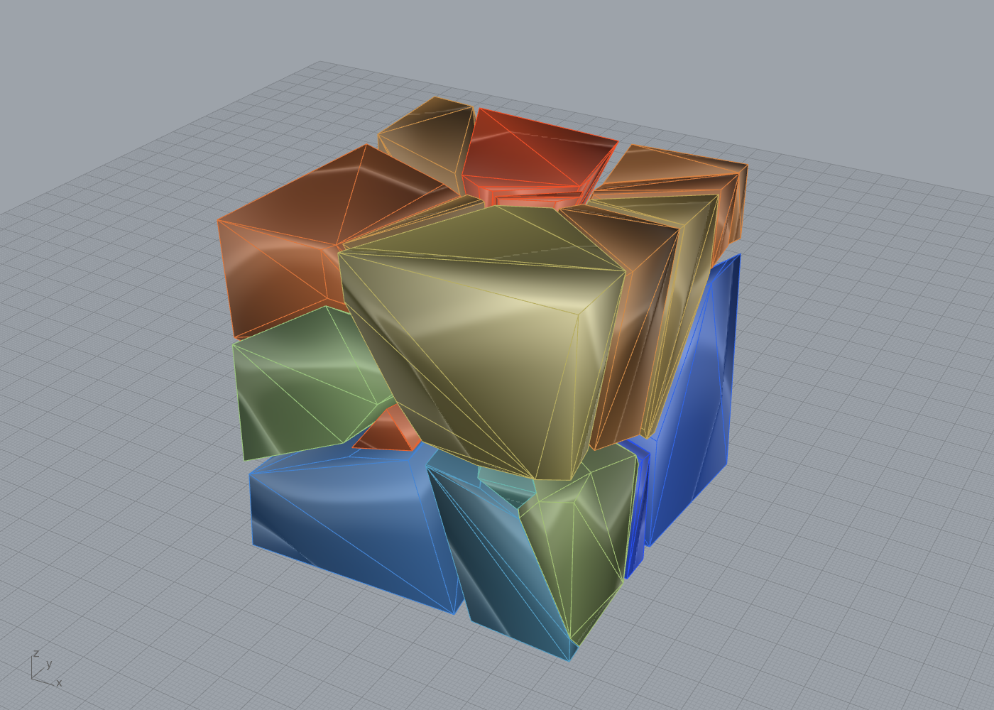
15. Evolution: From Baselines to the Current System¶
This chapter is cross-cutting. The preceding chapters describe each subsystem
as it stands; this one narrates how it got there. The repository is not a fresh
build. It is a sequence of measured deltas over named baselines, each baseline a
shipping implementation rather than a paper abstraction, each delta benchmarked
on the same instances before and after. The discipline is stated in the
research-workflow rules: the baseline is the current Frahan implementation, the
data is real (ETH1100 dry stone, Botticino GPR, Stanford scans), the metric is
mesh-accurate rather than bounding-box, and the truth criterion is live visual
validation, not a self-reported number (outputs/2026-06-03/RESEARCH_MATH_WORKFLOW_V2.md).
The originality scheme of chapter 90 governs the verdicts here: a thing is
called clean-room, evolved-fork, facade-over-primitives, direct-port,
vendored-library, original-research, or wrapper-of-native, with
file-and-line or commit evidence and a licensing flag where one applies. The
OpenNest-lineage nester used in the 2D benchmarks is named the reference
physics nester; no competitor source sits in this tree. Every number below
traces to a committed benchmark output or an [Algorithm] attribute.
The evolution has a shape. Six threads each moved a baseline forward: the 2D
nester walked from an overlap-tolerant placement rule to a hole-aware exact
solver; the 3D packer moved from a heightmap proxy to mesh-accurate collision
with physics settling; the quarry block-cutter gained a full-3D pose and three
new Pareto axes; the masonry stack grew from a force-only check to a coupled
kinematic certificate and an executable imposition metric; the GPR layer added
crack-aware recovery and wire-saw-separable yield; and the surface packers and
the BFF runtime were rebuilt onto the hardened nesting engine and a single static
binary. The recurring lever across all of them is the shared numeric-hygiene
finding from the ROSES synthesis: recenter before computing, use a
scale-relative epsilon, and route booleans through a robust kernel
(ROSES_top10_fabrication_synthesis.md, section 6).
15.1 Two-dimensional nesting: V506 to NFP-BLF to HoleNest to CNH¶
This is the longest and best-instrumented thread, and it sets the pattern for the chapter.
15.1.1 The baseline and its defect¶
The originally shipped nester is IrregularSheetFillV506 (FreeNest, GUID
D5E7A2B1-...). It is an NFP-assisted bottom-left placement that, by design,
permits a bounded overlap controlled by a Trim Tolerance and then
boolean-trims the contact. At the default Trim Tolerance of 0.1 it produces
visible overlaps; this is documented behaviour, not a fault (KB-6/KB-7;
examples/10_pack2d/README.md). The defect for fabrication is precisely this:
"packed" can mean "overlapping by up to the trim tolerance," which is not a
cut-ready layout.
15.1.2 First delta: the complete feasible region (V506 to FreeNestX)¶
IrregularSheetFillNfpBlf (FreeNestX, GUID 2d351646-...) re-derives the
placement so that the feasible set is the complete inner-fit-minus-no-fit
region, making zero overlap a hard constraint of construction rather than a
post-hoc trim. For a part \(B\) at fixed rotation on sheet \(S\) with holes \(\{H_l\}\)
and placed parts \(\{A_k\}\),
and the placement is the lexicographically lowest-then-leftmost vertex of that
region (Burke et al. 2006; Bennell and Oliveira 2009). The measured improvement
is recorded in source: a mean wasted-area cut of 53.9% against V506 at zero
overlap, validated against a Python reference
(IrregularSheetFillNfpBlf.cs:21-22;
outputs/2026-06-03/pack2d_nfp_evolution/CHECKPOINT_4.md). FreeNestX is the only
zero-overlap packer in the study to cross 80% utilisation with holes (82.0% to
89.6% on the hole fixtures, examples/10_pack2d/README.md).
Originality. FreeNestX is an evolved-fork of V506: same NFP/BLF lineage, but a re-derived complete feasible region replaces the overlap-then-trim contract, with the 53.9% waste-cut measured delta (
IrregularSheetFillNfpBlf.cs:18-27; commit46ae0d2).
15.1.3 Second delta: holes, a native kernel, and a depth certificate (CNH)¶
ContactNfpHoleNester (HoleNest, GUID D5F10019-...) evolves FreeNestX with
capabilities the fork lacks, and moves the engine out of the Grasshopper project
into the Rhino-free Frahan.StonePack.Core. The before/after of the engine
properties is the clearest single table in the thread.
| Property | V506 (FreeNest) | FreeNestX | CNH / HoleNest |
|---|---|---|---|
| Overlap guarantee | bounded, trimmed | zero by construction | zero, depth-certified always-on |
| Sheet holes | no | yes (no-fit only) | yes + part-in-part-hole nesting |
| Rotations | fixed list | fixed list | base + contact-adaptive edge alignment |
| Rect instances | general path | general path | exact integer shelf fast-path |
| Multi-sheet | no | no | greedy overflow |
| Rhino-free | no | no | yes (CI-benchmarkable) |
| Kernel | managed Clipper2 | managed Clipper2 | + native batched nfp_kernel.dll |
The three research increments are the contact-adaptive rotation set (augment the
uniform base \(\{0,\tfrac{\pi}{2},\pi,\tfrac{3\pi}{2}\}\) with edge-alignment angles
\(\theta=\alpha_h-\alpha_p\) and its flip \(\theta+\pi\)), the part-in-part-hole IFP
nesting (a filler's legal translations into a host hole \(G\) are exactly
\(\mathrm{IFP}(B,G)=\bigcap_{v\in\operatorname{hull}(B)}(G-v)\)), and the
distance-based penetration certificate with a single micro-retreat along the
measured penetration vector. These are derived in full in chapter 1; the point
here is the arc, not the algebra. The native kernel wraps nfp_kernel.dll, which
vendors official Clipper2 (BSL-1.0) unmodified, giving a measured 8x on the
batched-NFP path with only the marshalling owned in-repo (NativeNfpKernel.cs:10-22;
commit ec8a060).
15.1.4 Third delta: the rect fast-path and the keep-best fix¶
CNH v2 added a rectangle shelf fast-path: when every loop is an axis-aligned
rectangle, the NFP and IFP degenerate and the solve reduces to interval
arithmetic with no Clipper calls, using the exact integer rotation map
\((x,y)\mapsto(-y,x)\) so there is no trigonometric round-off
(ContactNfpHoleNester.cs:635-738). A completeness fallback discards the
fast-path result and runs the general engine if the sparser candidate set strands
any part (about 1 in 4000 in fuzzing). Multi-start keep-best runs \(K\)
deterministic part orders and keeps the densest valid layout. This last lever
carried a real bug worth recording because it shows the discipline at work: the
first multi-start landing computed candValid but never wrote cand.Valid, so
the keep-best comparison always saw false and degraded to "keep the last order
tried," which regressed the 60-irregular instance from 47 to 46 placed. The
verify pass root-caused it (not the NFP cache, which is structurally fresh per
pass, but the selection write), and the fix tracks a bestValid local. Post-fix,
\(\mathrm{placed}(K{=}4)\ge\mathrm{placed}(K{=}1)\) on all twelve tight instances
and the densest 90-irregular result of any engine in the study (0.735) is
HoleNest multi-start (outputs/2026-06-13/twod_decision/THREE_WAY_HEAD_TO_HEAD.md;
commit f4657e4).
15.1.5 The honest head-to-head¶
The 2026-06-13 three-way study put vanilla OpenNest (the reference physics nester, built from committed HEAD), its evolved hole/ThetaWise fork, and HoleNest through the same instances, with an independent shapely checker scoring every output so no engine's self-report is trusted.
| Lane | Reference physics nester | HoleNest | Reading |
|---|---|---|---|
| Irregular density (60/90 parts) | 0.751 / 0.710 | 0.730 / 0.711 | within ~3%, a wash |
| Rectangles (validity + speed) | 1 overlap on 20-rect; 0.5-1 s | 0 overlap; 5-54 ms | HoleNest 15-100x, always valid |
| Outline strip density (Sparrow) | wins by 6-10% | loses | honest boundary, unchanged |
| Determinism | stochastic relaxation | deterministic | reproducible cut layouts |
The honesty boundary is held in source: on pure outline strip packing the
reference physics nester still wins density by 6 to 10 percent, and no universal
"2x better" claim is made there. HoleNest's win is the hole-aware lane (where the
reference is invalid because it ignores holes), the rectangle lane (speed and
validity), and the determinism property. On the true-hole lane CNH is
54x faster and valid where Sparrow is invalid, and the rect fast-path is
about 22,000x faster (HOLE_PACKER_MATH_AND_BENCHMARK.md, sections 2-3).
15.1.6 The consolidation ruling¶
The thread ends in an architecture decision rather than another algorithm. A
2026-06-13 code-and-math-and-performance comparison found that as exposed in the
shipped components, HoleNest is a strict superset of FreeNestX: FreeNestX's
component calls only the 7-argument legacy constructor that forces the
concave-overlap verify off (KB-4), so its advanced math (multi-start, compaction,
GLS reinsertion) is dormant dead code unreachable from the canvas. The ruling is
fold-then-hide: port FreeNestX's eight unique UI features into HoleNest first, so
the fold is honest, then mark FreeNestX [Obsolete] and GH_Exposure.hidden
with its GUID preserved. The older V1/V2/V3/V506 standalones are already hidden
(outputs/2026-06-13/twod_decision/FREENESTX_VS_HOLENEST_DECISION.md,
TWOD_PACKER_ARCHITECTURE_DECISION.md). This is the 2D-V-solver phase-out the
collaborator-readiness plan mandated (EVOLUTION_PLAN_COLLAB_READY.md, HITL
ruling row 2).
15.2 Three-dimensional packing: heightmap proxy to mesh-accurate plus settle¶
The shipped 3D baseline is Pack3DIrregularContainerComponent (GUID
B3E8A42F-...) over GreedyMeshHeightmapPacker: a greedy deepest-bottom-left
placement on a per-cell vertical-interval ("heightmap column") collision of
mesh-derived footprints, scoring height growth against a back-left compactness
bias (Park and Han 2024; Pack3DIrregularContainerComponent.cs:18). Its defect,
stated in the plan, is that it packs footprint proxies, not true mesh
geometry: parts stack on columns rather than nesting into concavities, there is no
settling, and the reported fill is bounding-box based, so "packed" overstates true
density and says nothing about whether the pile is stable
(outputs/2026-06-03/pack3d_evolution/PLAN.md, section 1).
The evolution replaced the proxy with two stages. The constructive seed voxelises each real ETH1100 stone and places it by deepest-bottom-left over true-3D FFT feasibility (~33 to 37% compactness). Then a Bullet rigid-body settle drops the seeded poses under a gravity ramp with Coulomb friction and convex-decomposition (CoACD) collision, closing the voxel-quantisation gaps into real contact. The measured arc on real stones, with the honest mesh-volume compactness metric, is:
| Stage | N | placed | compactness | interpenetration | COM-stable |
|---|---|---|---|---|---|
| heightmap baseline (B3E8A42F) | 30 | 30 | 33.8% | ~0 | 57% |
| constructive seed | 30 | 30 | 32.6% | ~0 | 67% |
| + physics settle | 30 | 30 | 35.7% | ~0 | all at rest |
| heightmap baseline | 60 | 32 | 33.x% | ~0 | - |
| constructive seed | 60 | 32 | 36.9% | ~0 | 78% |
| + physics settle | 60 | 32 | 38.7% | ~0 | all at rest |
The honest finding is recorded against the original "beat it 2x" directive: the
physics settle improves on the constructive seed (32.6 to 35.7%, 36.9 to 38.7%)
and on the shipping baseline (33.8%), but by ~1.05 to 1.15x, not 2x, because
greedy irregular-stone packing plateaus around 33 to 39% and a literal 66% sits
above the physical ceiling without active void-insertion and a snug container
(outputs/2026-06-03/pack3d_evolution/CHECKPOINT_4.md). The win the settle does
deliver is qualitative as much as quantitative: a physically valid pile, every
stone at rest, zero interpenetration, which is the "complete packing, not bounding
boxes" deliverable the proxy packer could not produce.
The backend decision was deliberate and is itself evolution evidence. Bullet (via
BulletSharp.x64 0.12.0, zlib, double precision) was chosen over Kangaroo 2
because Kangaroo's position-based rigid collision has no friction and its author
states it "isn't suitable for stacking"; Kangaroo is kept only for the 2D
Trencadis soft-settle (BULLET_PHYSICS_BACKEND.md). The dev pybullet harness and
the shipped BulletSettleService wrap the same engine, so the dev-proven numbers
transfer. The result is Settle 3D (Physics) (GUID 134785ac-...), labelled as
the evolved volume packer while the heightmap components remain the validated
baseline, exactly the "keep one highly evolved 3D packer, supersession-document
the rest" ruling (PackSettle3DComponent.cs:29-46; EVOLUTION_PLAN_COLLAB_READY.md).
Originality. The mesh-accurate seed plus drop-settle is an evolved-fork of the heightmap baseline with a measured (modest, honest) compactness delta and a new stability guarantee. The Bullet settle credits Zhuang et al. (2024) for dynamics-based packing of irregular 3D objects, Bullet (Coumans) via BulletSharp, CoACD (Wei et al. 2022) for convex pieces, and Heyman (1966) for the COM-over-support gate (
PackSettle3DComponent.cs:29-35). The settle service and CoACD path are wrapper-of-native / vendored-library at the engine boundary; the seed-and-compose orchestration is ours.
15.3 Quarry block-cutting: BlockCutOpt 2020 to v2¶
The quarry thread takes a published serial algorithm and adds dimensions to it.
The baseline is Elkarmoty, Bondua and Bruno's (2020) BlockCutOpt: a brute-force
pose sweep that maximises the number of intact blocks a cutting lattice extracts
from a fractured deposit, with the lattice rotated only by yaw \(\psi\) about the
vertical. The repository's faithful transcription is BlockCutOptSolver (a
clean-room pose-grid argmax, bit-identical to a serial reference,
BlockCutOptSolver.cs:108-135).
The v2 increments are catalogued by improvement number in chapter 3 and summarised here as a before/after:
| Axis | BlockCutOpt 2020 | Frahan v2 | Evidence |
|---|---|---|---|
| Lattice pose | yaw \(\psi\) only | full 3D \(R=R_z(\psi)R_x(\theta)R_y(\phi)\) (I1) | CuttingGrid.cs:84-110 |
| Intersection test | full mesh scan | OBB-triangle 13-axis SAT + BVH prune (I2/I4) | ObbTriangleIntersection.cs:10-16 |
| Objective | block count | four-axis Pareto: count, kerf, yield, value (I6/I11) | BlockCutOptParetoSolver.cs:82-95 |
| Cost model | none | BCSdbBV cutting-surface/value (Jalalian 2023) | BlockValueModel.cs:54-58 |
| Cut sequence | none | AMRR plane-sequence planner (I9/I12) | AmrrPlanner.cs:7-31 |
The pose generalisation is exact and back-compatible: setting \(\theta=\phi=0\) collapses the rotated basis \(U,V,W\) to \((\cos\psi,\sin\psi,0)\), \((-\sin\psi,\cos\psi,0)\), \((0,0,1)\), recovering the BlockCutOpt-2020 \(\psi\)-only behaviour bit-for-bit through a back-compat constructor. The new objective adds Jalalian et al.'s (2023) BCSdbBV cutting-surface-area-over-value cost as a fourth Pareto axis, so the solver trades block count against waste and value rather than maximising count alone.
Originality. The pose-sweep core is clean-room from Elkarmoty et al. (2020); the full-3D pose (I1), the four-axis Pareto/Omni solvers (I6/I11), and the multi-scale
RecoveryCascadeare evolved-fork increments, each with an[Algorithm]attribute naming the Frahan improvement over the named baseline (BlockCutOptComponents.cs:98,:306-307). TheRecoveryCascadeheader was a flagged "novel" overclaim (E9) and has been softened to cite the BoEGE paper lineage; its lack of a GH consumer is an open roadmap item.
15.4 Masonry: RBE to CRA-coupled, plus Lambda and the generator¶
The masonry stack is the deepest evolution, executed as a planned sequence P0
through P7 (outputs/2026-06-10/masonry_evolution/EVOLUTION_PLAN_MASONRY.md).
15.4.1 Force-only to coupled-kinematic¶
The baseline verifier is Rigid-Block Equilibrium: a convex QP over contact forces
balancing self-weight, with Coulomb friction linearised to a polyhedral pyramid.
Force-only equilibrium has a known failure: Kao's H-model (a beam bridging two
columns, touching only on vertical faces with nothing underneath) is accepted by
RBE because a self-equilibrated horizontal friction squeeze appears to carry it,
even though nothing can produce that squeeze. The evolution (P2) couples statics
with virtual rigid-body kinematics so that a contact carries normal force only
where a consistent virtual motion lets it engage (Kao et al. 2022, Eqs. 8-14).
The repository does not ship IPOPT; it implements an alternating convex
certificate that is sound in the certifying direction, alternating a penalty RBE
force solve with a convex kinematic-certificate QP and a complementarity-driven
restriction step (CraStabilityChecker.cs:31-49). The H-model is now a
first-class regression: RBE accepts, CRA rejects
(CraStabilityCheckerTests.cs:83-105), and a compas_cra cross-fixture parity
suite pins agreement on shared cubes, stacks and an arch (commit 64ae069,
parity 5/5).
A correctness fix in the same thread is the friction linearisation direction. A
circumscribed \(K=4\) pyramid over-estimates the cone by up to
\(1/\cos(\pi/4)=\sqrt2\approx1.41\), certifying unstable walls as stable. The fix
inscribes the pyramid by shrinking the coefficient to
\(\mu_{\text{eff}}=\mu\cos(\pi/K)\), a conservative under-approximation that the CRA
checker now passes by default (FrictionConeBuilder.cs:105-130;
CraStabilityChecker.cs:90). For a stability verdict this is the
highest-consequence correction in the whole repository, because an optimistic
"stable" is the most dangerous failure mode (ROSES synthesis section 3).
15.4.2 Performance: dense Dykstra to sparse ADMM to exact-joint coupling¶
The solver path was rebuilt for scale (P1.1). The dense managed QP was replaced
with a CSR-sparse OSQP-style ADMM (Stellato et al. 2020) with full Ruiz
equilibration and per-row \(\rho\) to tame the mixed newton/metre/penalty scales
(AdmmQpSolver.cs:108-145). Separately, P1.2 stopped re-detecting contacts from
triangle meshes: a mesh contact detector splinters 40 stones into ~125
sub-interfaces and ~612 contact vertices, ill-conditioning the QP. The exact-joint
assembler emits one planar-quad interface per adjacent stone pair directly from
the shared generator edge, a ~27x speedup of the equilibrium QP on the 40-stone
generated wall (exact interfaces vs the ~612 splintered contact vertices the mesh
detector produced) and the reason CRA certifies generated walls
(commit a843027; Cra_GeneratedWall_Certified).
15.4.3 The new metrics: Lambda, the J interlock score, and the building¶
P3 evolved the wall generator (power diagram, Lloyd, coursing morph, sliver cull, and an original interlock score \(J\) penalising aligned running joints and "+" junctions). P4 made the top-down/bottom-up balance executable as the imposition metric
with \(\Lambda\approx1\) full imposition (sawn ashlar) and \(\Lambda\approx0\) pure
negotiation (stones as found). The Cyclopean datum is Clifford and McGee's (2018)
\(\Lambda\approx0.27\); the repository reports \(\Lambda=0.194\) on ETH1100, better
than the datum (StoneCellAssignmentEthBenchmarkTests.cs:14). P5 upgraded the
rubble drop-settle objective (Furrer support/COM plus Johns under-void candidate
ranking), P6 added the xBIM IFC terminal, and P7 composed it all into a
multi-container IFC castle (one .ifc, 8 containers, 123 parts, each
CRA-certified; commit 6e684b5). Lambda, \(J\), and the CRA instability field are
the three numbers every masonry example reports from P4 onward.
Originality. RBE and the ADMM solver are clean-room from cited papers; the CRA soundness certificate, the \(J\) interlock metric, and the Lambda formalisation are original-research (A-candidate, prior-art sweep pending per AGENTS.md section 9); the exact-joint assembler is clean-room geometry; the carve-back is facade-over-primitives over the CGAL boolean kernel. One citation flag remains open:
BestFitPackComponent.cs:30attributes a likely fabricated 2017 NCCR paper whose real lineage is Furrer (2017) / Johns (2020) (E5).
15.5 GPR additions: RecoveryCascade and the staged guillotine packer¶
The GPR thread is additive rather than a replacement: it gave the quarry packers
fracture awareness. RecoveryCascade is a multi-scale reject-recover packer that
partitions a candidate block into kept and cracked regions by whether any DFN
triangle intersects it, recurses at a finer scale on the cracked remainder, and
reduces exactly to the BlockCutOpt baseline at a single scale
(RecoveryCascade.cs:26-29, :91-119). FractureBlockPack is the
uncertainty-safe yield engine of example 09: a wire-saw staged guillotine
packer whose blocks are separable by full-width saw passes, trading raw density
for fabricability. The measured trade is recorded: mode-5 wire-saw-separable yield
49.3% at 100% separability versus a voxel-DLBF 53.3% at 0% separability, costed by
Jalalian's I11 saw objective (memory project_gpr_fracture_capability). Both are
folded into the same BoEGE master paper rather than a separate publication, and
the paper passed a five-reviewer re-review at accept.
Originality.
RecoveryCascadeis evolved-fork (multi-scale recursion over BlockCutOpt, reduces to baseline at \(S=1\));FractureBlockPackis facade-over-primitives, a self-contained recovery engine. A flagged risk is thatFractureBlockPackdoes not callRecoveryCascadeorBlockCutOptSolver, so a silent-disagreement between the two recovery paths is possible and is an open roadmap item.
15.6 Surface packers and BFF: onto the hardened engine and a single static exe¶
Two infrastructure evolutions land last. First, both surface packers (Pack
Surfaces, Pack On Surface) were moved off IrregularSheetFillV506 onto the
deterministic HoleNest engine (ContactNfpHoleNester.PackSheets: exact NFP-BLF,
multi-start, zero overlap) and adopted HoleNest's self-trigger background pattern
(previous result stays visible, live progress, stable bbox loop-guard hash) in
place of GH_TaskCapableComponent. The async lineage itself evolved: Sheet Nest
went async, was reverted to synchronous to kill an endless re-solve loop
(commit 0a56dfb), then restored as a self-trigger flag with a stable bbox hash
that progresses without starving or looping (7d46ec8). Back-compatibility was
held exactly: GUIDs unchanged, outputs unchanged, the four V506-only controls made
inert and documented (commit 05c7e82).
Second, the Boundary First Flattening runtime (Sawhney and Crane 2017, used by the
Surface Chart) was recompiled from the GeometryCollective source as a fully
static single executable via MSYS2 mingw64 with static SuiteSparse and OpenBLAS
archives. External dependencies drop to KERNEL32 and msvcrt only (objdump
verified); the deploy shrinks from ~67 MB across an exe plus 17 DLLs to ~38 MB
in one self-contained exe (install/tools: 18 files to 2). This also fixed a
latent break: the deployed bff-command-line.exe had shipped with none of its 17
DLLs, so BFF was non-functional from the .gha folder (exit 0, zero UVs). The
new exe needs no siblings, produces byte-identical UV flattening to the reference
build, and was validated end-to-end (dome to chart to 18/18 placed, valid, curves
exactly on surface; commit d1b5c5b).
Originality. The surface packers are facade-over-primitives recomposed onto the HoleNest engine; the integration delta is real (deterministic, verified, zero-overlap nesting replacing an overlap-tolerant one). BFF remains a vendored-library (Sawhney and Crane 2017); the static-link rebuild is a packaging change, not an algorithm change, and still owes a
THIRD_PARTY_NOTICESrow per the licensing register.
15.7 Status and what is left¶
The evolution is real but incomplete, and the honest gaps are tracked.
- 2D fold not yet executed. The fold-FreeNestX-into-HoleNest port (eight UI features, then hide) is decided but not landed; until it is, the plugin ships two NFP nesters and FreeNestX's shipped path still runs no concave-overlap verify (KB-4). Medium.
- 3D "2x" narrative. The compactness gain over the heightmap baseline is ~1.05 to 1.15x, not the original 2x target; the ROSES roadmap keeps a mesh-accurate-port item open to fix the narrative and push past ~35% with active void-insertion. Medium.
- CRA convergence at scale. The ADMM degrades past ~50 interfaces; the LS-first certificate mitigates wall-scale checks but per-element verification remains the pattern for large mixed assemblies, and conditioning to 300 interfaces is an open benchmark item. High.
- GPR recovery-path divergence.
FractureBlockPackandRecoveryCascadeare separate engines with no shared call path; a silent-disagreement test is owed. High. - Open citation and licensing flags. The fabricated Best-Fit citation (E5),
the "Phase correlator FFT" wording over a direct-correlation implementation, and
the missing
THIRD_PARTY_NOTICES.mdfor the BFF numeric stack must close before external review (AGENTS.md section 9; licensing register rows 10, 13). Medium. - Prior-art sweeps pending. The \(J\) interlock metric, the Lambda formalisation, the CRA certificate, and the projection bootstrap are all A-candidate; none may be asserted "novel" until the sweep completes. Medium.
The one-line reading: across six threads the repository moved from overlap-tolerant, proxy-based, force-only, single-axis baselines to zero-overlap-certified, mesh-accurate, kinematically-coupled, multi-axis successors, every step measured against the shipping predecessor on real data, with the modest-but-honest deltas reported as modest and the genuine wins (validity, determinism, stability, fabricability) reported where they are real.
References (this chapter)¶
- Burke, E.K., Hellier, R., Kendall, G., Whitwell, G. (2006). A new bottom-left-fill heuristic algorithm for the two-dimensional irregular packing problem. Operations Research 54(3):587-601. DOI 10.1287/opre.1060.0293.
- Bennell, J.A., Oliveira, J.F. (2009). A tutorial in irregular shape packing problems. Journal of the Operational Research Society 60(S1):S93-S105. DOI 10.1057/jors.2008.169.
- Park, J., Han, S. (2024). Tree-packing for irregular 3D containers (tree-search 3D bin packing / orthogonal-block packing).
- Chehrazad, R., Roose, D., Wauters, T. (2025). A fast and scalable deepest-left-bottom-fill algorithm for the 3D bin packing problem. International Journal of Production Research 63:6606-6629. DOI 10.1080/00207543.2025.2478434.
- Zhuang, Q., Chen, Z., He, K., Cao, J., Wang, W. (2024). Dynamics simulation-based packing of irregular 3D objects. Computers and Graphics 123:103996. DOI 10.1016/j.cag.2024.103996.
- Wei, X., Liu, M., Ling, Z., Su, H. (2022). Approximate convex decomposition for 3D meshes with collision-aware concavity and tree search (CoACD). ACM Transactions on Graphics 41(4):42. DOI 10.1145/3528223.3530103.
- Elkarmoty, M., Bondua, S., Bruno, R. (2020). Mechanized in-situ determination of joint-related and yield-related rock-mass parameters during dimension stone block extraction. Resources Policy 68:101761. DOI 10.1016/j.resourpol.2020.101761.
- Jalalian, M.H., Bagherpour, R., Khoshouei, M. (2023). Environmentally sustainable mining in quarries to reduce waste production and loss of resources using the developed optimization algorithm (BCSdbBV). Scientific Reports 13:22183. DOI 10.1038/s41598-023-49633-w.
- Kao, G.T.-C., Iannuzzo, A., Thomaszewski, B., Coros, S., Van Mele, T., Block, P. (2022). Coupled Rigid-Block Analysis: stability-aware design of complex discrete-element assemblies. Computer-Aided Design 146:103216. DOI 10.1016/j.cad.2022.103216.
- Stellato, B., Banjac, G., Goulart, P., Bemporad, A., Boyd, S. (2020). OSQP: an operator splitting solver for quadratic programs. Mathematical Programming Computation 12:637-672. DOI 10.1007/s12532-020-00179-2.
- Heyman, J. (1966). The stone skeleton. International Journal of Solids and Structures 2(2):249-279. DOI 10.1016/0020-7683(66)90018-7.
- Furrer, F., Wermelinger, M., Yoshida, H., Gramazio, F., Kohler, M., Siegwart, R., Hutter, M. (2017). Autonomous robotic stone stacking with online next best object target pose planning. IEEE ICRA. DOI 10.1109/ICRA.2017.7989273.
- Johns, R.L., Wermelinger, M., Mascaro, R., Jud, D., Gramazio, F., Kohler, M., Chli, M., Hutter, M. (2020). Autonomous dry stone. Construction Robotics 4:127-140. DOI 10.1007/s41693-020-00037-6.
- Clifford, B., McGee, W. (2018). Cyclopean Cannibalism: a method for recycling rubble. ACADIA 2018 (Disciplines and Disruption).
- Sawhney, R., Crane, K. (2017). Boundary First Flattening. ACM Transactions on Graphics 37(1):5. DOI 10.1145/3132705.
Originality Matrix¶
Sole author: Independent Research. Open data, open source. No university affiliation.
This is the binding originality ledger for the thesis. Every shipped
component (or component family) across all fifteen chapters is classified
into exactly one originality class, with file-and-line evidence drawn from
its [Algorithm] attribute, its Core engine, and the committed benchmark.
The honesty convention of AGENTS.md §9 governs: a thing is called original
only with a prior-art sweep behind it, an extension of prior work is named as
such, and vendored third-party code is named by its upstream and licence. A
result is reported, not validated, until visually confirmed on the canvas.
The seven classes are:
- clean-room — built from published mathematics, no upstream source in the tree.
- evolved-fork — extends a documented baseline (in-repo or published) with a stated, measured delta.
- facade-over-primitives — a monolith composing our own published Core primitives; adds orchestration, not a new algorithm.
- direct-port — a line-by-line port of an external open-source library.
- vendored-library — we ship or link a third-party library unmodified; only the marshalling is ours.
- original-research — Frahan-novel, A-candidate pending a prior-art sweep.
- wrapper-of-native — a Grasshopper wrapper over a native exe or DLL.
Clean-room language note. The OpenNest-lineage physics nester referenced in
the benchmarks is named "the reference physics nester" (or "evolved fork");
no competitor source is copied into this tree. Academic sources are cited by
the [Algorithm] attribute model.
A component family that spans more than one chapter is detailed once at its primary chapter and cross-referenced elsewhere; the whole-repo summary counts each family once.
Chapter 01 — Two-Dimensional Nesting and Trencadís¶
| Component (family) | Class | Evidence |
|---|---|---|
| IrregularSheetFillNfpBlf / Freeform Sheet Nest (Exact NFP) (FreeNestX) | evolved-fork | [Algorithm] IrregularSheetFillNfpBlfComponent.cs:24-32 (Burke 2006 DOI 10.1287/opre.1060.0293; Bennell-Oliveira 2009 DOI 10.1057/jors.2008.169; Clipper2 BSL-1.0). Feasible-region contract IrregularSheetFillNfpBlf.cs:18-27. Clean-room math base; the evolved-fork delta is over V506's overlap-then-trim. Measured 53.9% mean waste-cut vs V506 at zero overlap (IrregularSheetFillNfpBlf.cs:21-22; outputs/2026-06-03/pack2d_nfp_evolution). |
| ContactNfpHoleNester / Sheet Nest (Hole-Aware) (CNH) | evolved-fork | [Algorithm] HoleNestComponent.cs:25-36 (clean-room NFP/BLF/IFP base + "Frahan ContactNfpHoleNester evolution study"). Core engine ContactNfpHoleNester.cs:10-33 (contract), :1281-1330 (contact rotations), :1332-1352 (IFP = intersect over hull vertices), :1777-1798 (penetration depth), :1728-1748 (micro-retreat), :635-738 (rect fast-path), :243-292 (multi-start). Benchmark outputs/2026-06-12/hole_packer_evolution: 60.7 ms valid 12/12 vs reference physics nester (Sparrow) 3255 ms invalid (~54x and valid where the reference fails); fast-path 0.148 ms (146x native shelf). Also the engine consumed by chapters 07 and 14. |
| IrregularSheetFillV506 / Freeform Sheet Nest (FreeNest) | evolved-fork | [Algorithm] Pack2DIrregularSheetV506Component.cs:23-27 (NFP-assisted BLF; Bennell-Oliveira tutorial). [Obsolete] Exposure=hidden :56-57. Overlap-then-trim documented by design in examples/10_pack2d/README.md (KB-6/KB-7). The FreeNestX evolution baseline; now phased out per the 2D-V-solver decision. |
| IrregularSheetFillComponent / Frahan Sheet Pack (Unified) (FreeNestU) | facade-over-primitives | [Algorithm] IrregularSheetFillComponent.cs:32-33 ("Variant dispatcher V1/V2/V3/V506; Frahan-original strategy selector") over Burke 2007 + Bennell-Oliveira 2008. Adds no new algorithm; dispatches existing nesting variants behind one box. |
| NfpPack2DComponent / 2D NFP Pack | clean-room | [Algorithm] NfpPack2DComponent.cs:11-12 (Burke 2007 DOI 10.1016/j.ejor.2006.03.011; Bennell-Oliveira 2008 DOI 10.1057/jors.2008.169). Citation-only; no upstream nesting source in the tree. |
NativeNfpKernel (nfp_kernel.dll) |
vendored-library | NativeNfpKernel.cs:10-22: "native/nfp_kernel/nfp_kernel.dll, vendored official Clipper2 C++" on the Int64 lane; only the marshalling is ours. Clipper2 BSL-1.0 (no copyleft). Consumed at ContactNfpHoleNester.cs:924-930. ~8x batched-NFP wall-time (NativeNfpKernel.cs:10-22). |
| Pack2DTrencadisCatalogComponent / Trencadis Catalog Pack | facade-over-primitives | [Algorithm] Pack2DTrencadisCatalogComponent.cs:37-38 ("CVD-Lloyd interior seeding" Lloyd 1982; "Slab-partitioned Voronoi catalog; Frahan-original Trencadis extension"; precedent Battiato 2013 :42). Composes CvdLloyd2d + HungarianAssignment primitives. 28/28 placed in 53 ms (examples/12_trencadis/README.md). |
| CvdLloyd2d (CVD-Lloyd seed generator) | clean-room | CvdLloyd2d.cs:14-22 (uniform-density CVD; matches wiki/primitives/cvd_lloyd.md); Lloyd 1982 relaxation, grid-discretised, stop at half-grid-step move (:30-108). Math-only, no upstream code. |
| HungarianAssignment (Kuhn-Munkres O(n³)) | clean-room | HungarianAssignment.cs:11-15 ("classical shortest augmenting path formulation (Bourgeois-Lassalle 1971), standard textbook implementation"); potentials u/v with non-negative reduced costs (:23-85). Textbook math (Kuhn 1955 / Munkres 1957 / Bourgeois-Lassalle 1971), no upstream code. Reused by the masonry Lambda engine (Ch. 05) and the Trencadis catalog. |
| Pack2DTrencadisComponent / Trencadis Pack (greedy NFP-slide) | facade-over-primitives | [Algorithm] Pack2DTrencadisComponent.cs:37-38 ("Trencadis greedy pack basic" Gaudi Park Guell; "NFP boundary slide" Minkowski-difference sampler). Battiato 2013 sect 4 cut budget TrencadisFill.cs:13-27. Standalone box is a skeleton returning empty (examples/12_trencadis/README.md) — see Roadmap (ghost component). |
| Pack2DTrencadisDynamicComponent / Trencadis Dynamic Settle | facade-over-primitives | [Algorithm] Pack2DTrencadisDynamicComponent.cs:61-62 ("Trencadis dynamic settle" Frahan-original; "Kangaroo 2 goal-based physics" Daniel Piker). 55.1% physics vs 52.7% greedy (examples/12_trencadis/README.md). |
| TrencadisEdgeMatchComponent / Trencadis EdgeMatch | facade-over-primitives | [Algorithm] TrencadisEdgeMatchComponent.cs:28-29 ("EdgeMatch-powered Trencadis pack"; "Frahan-original alternative to Battiato 2013 CVD+GVF stack"; "Beam-search assembly solver" Frahan-original). Composes the EdgeMatching primitives (Ch. 08). |
| Pack2DTrencadisPipelineComponent / Trencadis Pipeline | facade-over-primitives | [Algorithm] Pack2DTrencadisPipelineComponent.cs:59-62 (greedy pack + NFP slide + CVD-Lloyd seeding + Kangaroo 2 settle, all cited to in-repo primitives + Daniel Piker physics). |
Chapter 02 — Three-Dimensional Packing and Settling¶
| Component (family) | Class | Evidence |
|---|---|---|
Heightmap packers (GreedyHeightmapPacker, OrientedMeshHeightmap, MeshPileHeightmap, IrregularMeshContainer) |
clean-room | Deepest-bottom-left / DLBF substrate cited to Chehrazad, Roose, Wauters 2025 (Pack3DIrregularComponent.cs:20-23, GUID E36C3F7D). Two-surface mesh-pile proxy, per-cell vertical-interval test, six-orientation down-axis search, ray-cast container labelled "Frahan-original mesh-pile heightmap" (Pack3DMeshHeightmapComponent.cs:20-21, GUID A16D6426). Heightmap.cs:8-69, OrientedMeshHeightmap.cs:8-292, MeshPileHeightmap.cs:79-271, IrregularMeshContainer.cs:52-176. Citation flag: sibling Pack3DIrregularContainerComponent.cs:18 credits "Park and Han 2024" ([R8], no DOI, placeholder) for the same method — reconcile (Roadmap medium). |
| BlockPackTreeComponent / Block Pack (Tree) (DLBF guillotine forest) | evolved-fork | [Algorithm] BlockPackTreeComponent.cs:30-31 (Kim 2025 Computation 13:211 DOI 10.3390/computation13090211, CC BY 4.0; Jalalian 2023 BCSdbBV cut-area term). GUID C2D3E4F5. Frahan deltas: deterministic master seed, saw kerf, forbidden boxes, parallel forest (:22-28, :154-158). Live 12/12, score 65.11, deterministic (examples/11_pack3d/README.md). |
| Dlbf3dMixedSizePacker (3D deepest-left-bottom-fill mixed-size) | clean-room | Dlbf3dMixedSizePacker.cs:8-37, :186-220 (lexicographic deepest-left-bottom), :127-143 (best-of-orientation, default off). [Algorithm] BlockCutOptHeterogeneousComponents.cs:42 (Chehrazad, Roose, Wauters 2025, DOI 10.1080/00207543.2025.2478434). Standalone as Frahan Mixed-Size Block Pack 3D (GUID F2D0BC18). |
HeteroExt (FrahanHeterogeneousExtractionComponent) |
facade-over-primitives | [Algorithm] BlockCutOptHeterogeneousComponents.cs:169 ("Frahan-original ... Composes Elkarmoty 2020 and Chehrazad 2025 ... the composition and the heterogeneity model are the contribution"). GUID F2D0BC19. Composes BlockCutOpt + DLBF + monument packer; [RelatedComponent] back-pointers to the standalone primitives (:170-176). Detailed once here; also in Ch. 03 / Ch. 13 / Ch. 14. |
Settle 3D (Physics) (PackSettle3DComponent / BulletSettleService) |
clean-room (over vendored) | [Algorithm] PackSettle3DComponent.cs:29-35 (Zhuang et al. 2024 DOI 10.1016/j.cag.2024.103996 dynamics packing; Bullet via BulletSharp zlib; CoACD Wei et al. 2022; Heyman 1966 COM-over-support). GUID 134785ac. Gravity-ramp seeding BulletSettleService.cs:135-141, centroid-relative decode :62-70. The dynamics framing + gravity-ramp + transform decode are ours; Bullet/BulletSharp/CoACD are vendored. |
| SlabCutByFractures / slab half-space cutter | clean-room | [Algorithm] SlabCutByFracturesComponent.cs:33-39 ("Frahan-original" convex half-space clipping, Sutherland-Hodgman family; Goodman-Shi 1985 block theory SlabCutter.cs:29-33). GUID C2B3D4E5. Exact for convex input; opt-in CGAL backend for non-convex (:84-92). |
| Slab Cut By Tool Mesh (CGAL) / Vertical Fracture Planes From Curves | wrapper-of-native / clean-room | CGAL boolean path is wrapper-of-native over the GPL frahan_cgal shim (licensing register row 4); the curve-to-plane lift (GUID F2D05A09) is clean-room elementary geometry. |
| Example 15 statue-to-blocks decomposition (bed-bounded real-face grid) | facade-over-primitives | Study-level composition: 0.5 m grid × CGAL boolean over a Geogram-cleaned 2-manifold; recovered-volume ratio 1.0000 by VolumeMassProperties (examples/15_statue_to_blocks/README.md). Composes Geogram clean-up + CGAL boolean; no Core algorithm class. |
Chapter 03 — Quarry Block-Cutting Optimization¶
| Component (family) | Class | Evidence |
|---|---|---|
| BlockCutOptSolver (pose-sweep max-cover) | clean-room | Core BlockCutOptSolver.cs:108-135 (pose grid + parallel argmax, bit-identical to serial reference), :261-268 (kerf film). GH BlockCutOptSolveComponent guid F2D0BC02 [Algorithm("BlockCutOpt brute-force search","Elkarmoty Bondua Bruno 2020, Resources Policy 68:101761",Doi=10.1016/j.resourpol.2020.101761)] BlockCutOptComponents.cs:97. README.md:46-50: upstream is private C++, no source in tree. |
| CuttingGrid full-3D rotation (I1 pose tilt) | evolved-fork | CuttingGrid.cs:84-110 (pre-multiplied U,V,W), :77-78/127-129 (kerf pitch). [Algorithm("Full 3D rotation grid","Frahan I1 improvement over Elkarmoty 2020 psi-only")] BlockCutOptComponents.cs:98. README.md:185. psi-only back-compat constructor OrientedBlock.cs:40-50 collapses to BlockCutOpt 2020. |
| ObbTriangleIntersection + TriangleAabbBvh (I2/I4 predicate) | clean-room | ObbTriangleIntersection.cs:10-16 (13-axis SAT), used BlockCutOptSolver.cs:243-256. [Algorithm("Triangle-AABB BVH pruning","Akenine-Moller 2001 fast 3D triangle-box overlap")] BlockCutOptComponents.cs:99. README.md:186-188. |
| BlockCutOptParetoSolver + BlockCutOptOmniSolver (I6/I11 four-axis) | evolved-fork | BlockCutOptParetoSolver.cs:82-95, ParetoPoint.Dominates ParetoPoint.cs:54-71, BlockCutOptOmniSolver.cs:115-178. GH BlockCutOptOmniSolveComponent guid F2D0BC04 [Algorithm] pair BlockCutOptComponents.cs:306-307 (Elkarmoty 2020 + Jalalian 2023 BCSdbBV). README.md:190,195. |
| BlockValueModel BCSdbBV cost objective (I11) | clean-room | BlockValueModel.cs:54-58 (SurfaceArea S=2(LxLy+LyLz+LxLz)), :22-27 (BV). ParetoPoint.cs:12. README.md:195 cites Jalalian, M.H. et al. 2023 DOI 10.1038/s41598-023-49633-w. Faithful axis from published math. |
| RecoveryCascade (multi-scale reject-recover) | evolved-fork | RecoveryCascade.cs:26-29 (W(R,s) recursion), :91-119 (kept/cracked partition by !bvh.AnyTriangleIntersects), :21-24 (reduces to baseline at one scale), :31-36 (BoEGE / Murugean 2026 cite softening, flag E9). No GH consumer — see Roadmap (high). Also detailed in Ch. 04. |
| AmrrPlanner (I9 plane sequence) + SharedEdgeSlicer (I12) | clean-room | AmrrPlanner.cs:7-31, :132-178 (cut loop), :85 (AMRR = removed volume / cutting time). GH BlockCutOptAmrrPlanComponent guid F2D0BC03 [Algorithm("AMRR in-block plane-sequence cutting","Shao, Liu, Gao 2022")] BlockCutOptComponents.cs:215. README.md:193,196 (Shao 2022 DOI 10.3390/pr10040695; Minetto 2017 DOI 10.1016/j.cad.2017.07.001). |
| FractureBlockPack (uncertainty-safe yield, example 09) | facade-over-primitives | FractureBlockPackComponent.cs:27 (class), :37 (guid A7E0B0F3), :9-25 header: self-contained recovery engine that does NOT call RecoveryCascade / BlockCutOptSolver / Dlbf3dMixedSizePacker (silent-disagreement risk — Roadmap high). Fully managed, no native shim. |
| HeteroExt (heterogeneous quarry extraction) | facade-over-primitives | See Ch. 02 row. [Algorithm] BlockCutOptHeterogeneousComponents.cs:169; DLBF [Algorithm] :42 (Chehrazad Roose Wauters 2025). |
| FrahanSawBedScheduleComponent (Saw Bed Schedule) | clean-room | [Algorithm("Greedy LPT list scheduling","Graham 1969, SIAM J. Appl. Math. 17(2):416-429",Doi=10.1137/0117039)] QuarryCutOptComponents.cs:336. Textbook LPT, no upstream code. |
| Extraction Order Optimizer | original-research | [Algorithm] note QuarryCutOptComponents.cs:223 "no published scheduling algorithm matched". A-candidate, prior-art sweep pending (Roadmap low). |
| Guillotine cut staging (examples 24/25) | facade-over-primitives | Standard staged guillotine cutting (Gilmore-Gomory 1965 lineage); the contribution is the rendered, in-order, fabricable saw plan on real geometry, not an algorithm (examples/24_guillotine_cut_sequence/README.md). |
| Bed-bounded hexahedra + flat/oblique frontier (example 08) | facade-over-primitives | Study-level construction in the example generator (bed-plane fitting + packing objective); REPORTED not gated (08_marble_cost_volume_metrics.json). |
Chapter 04 — GPR Fracture and Cavity Mapping¶
| Component (family) | Class | Evidence |
|---|---|---|
| GprFileReader + per-format readers (CSV/SEG-Y/MALA/pulseEKKO/IDS/GSSI) | clean-room / vendored-library | Per-format clean-room over open or public-domain specs (SEG-Y = SEG standard; pulseEKKO DT1/HD = USGS OFR 02-166, Lucius-Powers 1999; MALA/DZT/IDS decoded from open RGPR / BSD-3 readgssi). GprFileReader.cs:23-51. Dispatcher is a thin switch, no algorithm. Detailed by reader in Ch. 12. |
| RadargramProcessor filters (dewow / bg-removal / mute / t-gain / depth-equalize) | clean-room | Standard GPR processing (Annan 2009; Neal 2004), RadargramProcessor.cs:100-182,310-332. The contribution is the validated ordering and parameterisation, not the filters. |
| Fft (radix-2 Cooley-Tukey + Bluestein) | clean-room | Fft.cs:16-18,30-149. Numerical method (Cooley-Tukey 1965), not copyrightable; exact-length forward/inverse to match numpy.fft. |
| HilbertEnergy / analytic-signal envelope | clean-room | Fft.cs:159-185, RadargramProcessor.cs:293-308. Taner, Koehler, Sheriff 1979 complex-trace analysis, cited GprFractureExtractComponent.cs:44. |
| StoltMigration (f-k migration + cosine dip-taper) | clean-room (+ evolved anti-alias) | RadargramProcessor.cs:199-291, half-velocity :208, Jacobian :259-267, dip-taper :235-244. Stolt 1978, cited GprFractureExtractComponent.cs:44. The published method is clean-room; the cosine dip-taper is a small evolved anti-alias addition, not a new migration. |
| FractureExtractor (high-energy + dip-aware continuity) | evolved-fork | FractureExtractor.cs:8-159. Clean-room base = high-energy quantile + USGS Mirror Lake continuity (WRIR 99-4018C; Porsani 2006; Isakova 2021). The dip-aware shear-count continuity (:76-130) is the measured delta over the flat-horizon USGS test. GH GUID A7E0B0F1. |
| GprPresets (stone × frequency catalogue) | clean-room | GprPresets.cs:7-25. Calibration data, no algorithm; IsEmpirical flag (:22-24) distinguishes validated (marble_600, granite_160) from literature-default presets. |
| FractureSurface loft / reconstruct | clean-room / wrapper-of-native | Loft path clean-room elementary construction (FractureSurface.cs:42-110). Reconstruct path wrapper-of-native over geogram screened-Poisson (Kazhdan-Hoppe 2013, BSD-3 + bundled MIT PoissonRecon) and CGAL advancing-front (GPL), reached out-of-process (:112-139). |
| FractureUncertainty (position ladder + detection rung) | original-research | FractureUncertainty.cs:6-220. Three-rung position ladder (depth-growing velocity + time-zero + λ/4), detection rung with depth-aware Fresnel floor and P_det factorisation are the Frahan contribution; underlying physics cited (Porsani 2006; Xie 2021; Molron 2020; Dorn 2012). A-candidate, prior-art sweep pending. GH GprFractureSurface3DComponent.cs:30, GUID A7E0B0F2. |
| Kriging (simple kriging posterior) | clean-room | Kriging.cs:8-29. Ordinary kriging linear algebra (Cressie 1993; Rasmussen-Williams 2006); managed replacement for scikit-learn GPR. |
| BedrockSurface | clean-room | BedrockSurface.cs:7-93. Pure reduction + datum shift; deepest-reflector top-of-rock (Porsani 2006 / Isakova 2021). GH GUID A7E0B0F1 (GprBedrockSurface). |
| TinMerge (k-NN inverse-distance weighting) | clean-room | TinMerge.cs:54-122. Shepard 1968 IDW with a scale-relative radius and recenter; no upstream code. |
| TinPeelFilter (border-peel scan cleaner) | clean-room | TinPeelFilter.cs:7-163. Border-peel logic (long-edge / vertical-facet / cap predicates) ported from the Fade2D land-survey reference's peelOffIf, no upstream code; cited in CleanScanMeshComponent.cs:29-31, GUID A7E0B0F1. |
| Vector Fractures Loader (shapefile fracture map, example 26) | vendored-library | NetTopologySuite.IO.Esri (ESRI Shapefile / OGC Simple Features); strike binning and render clean-room. Detailed in Ch. 12. |
Chapter 05 — Masonry Equilibrium and Cyclopean Reassembly (CRA)¶
| Component (family) | Class | Evidence |
|---|---|---|
| Masonry Stability (RBE) | clean-room | [Algorithm] MasonryStabilityRbeComponent.cs:69-71 (Kao et al. 2022 CAD 146:103216; Whiting et al. 2009 RBE precedent; compas_cra MIT cited, not copied). Equilibrium math EquilibriumMatrixBuilder.cs:13-30,201-219; linearised Coulomb cone FrictionConeBuilder.cs:24-32; inscribed-pyramid correction :105-130. Wires the sign-corrected BuildPhysicsCorrected at :305, not the legacy Build. Convex-QP force+moment balance, compression-only normals. |
| Masonry Stability Check (CRA) | original-research | CraStabilityChecker.cs:17-50 (Kao H-model Eqs 8-11 cited); alternating-convex certificate :154-186 is NOT in compas_cra (which uses non-convex IPOPT). A-candidate, soundness-certifying direction proven; H-model regression CraStabilityCheckerTests.cs:83-105; compas_cra parity Program.cs:347-356. Rejects self-stressed states RBE wrongly accepts. GUID D5F10015. |
| AdmmQpSolver | clean-room | AdmmQpSolver.cs:6-51 (Stellato et al. 2020 OSQP, Math.Prog.Comp 12:637-672); ADMM iteration :182-256; masonry Ruiz equilibration :108-145. CSR-sparse, per-row rho. OSQP-style infrastructure with engineering deltas; no upstream OSQP source in tree. |
| Polygonal Wall (Generator) | original-research | PolygonalWallGenerator.cs:7-34 (power diagram :13-17), interlock metric J InterlockScore:310-384. A-candidate (Kim 2024 does sequencing, not generation; sweep pending — Legakis 2001 closest prior). Hover credits Kim 2024 / Clifford-McGee 2018 / Lloyd 1982 at PolygonalWallGeneratorComponent.cs:31-33. GUID D5F10014. |
| PolygonalWallAssembler (exact-joint) | clean-room | PolygonalWallAssembler.cs:8-30 exact planar-quad interface per adjacent pair from shared (u,v) edges; avoids mesh-contact-detector splintering of the equilibrium QP. Feeds the equilibrium builder; Cra_GeneratedWall_Certified Program.cs:335. |
| Stone Cell Match (Lambda engine) | original-research | StoneCellAssignment.cs:8-37 (Lambda / lambda / gap formulas); composes the reused HungarianAssigner:141-145 and voxel kernel. A-candidate Lambda formalisation (Clifford-McGee measured 0.27, never formalised; assignment published in Bruetting 2019 / Bukauskas 2019); ETH1100 datum StoneCellAssignmentEthBenchmarkTests.cs:14,95; reported Lambda = 0.194. GUID D5F10016. |
| StoneCarveBack (Cyclopean) | facade-over-primitives | StoneCarveBack.cs:9-29 cites Clifford & McGee 2018 anti-nesting; exact booleans through the in-repo CgalMeshBoolean:23-28 primitive; volume-validated in the battery. Composes booleans, adds no new algorithm. |
| Rubble Wall Settle | clean-room | [Algorithm] RubbleWallSettleComponent.cs:35-36 (Heyman 1966 limit-state); Core RubbleWallSettle.cs:9-32 from the signed-off Furrer 2017 / Johns 2020 prototype. Deterministic, non-penetrating, PCA flat-bedding + per-cell drop, Heyman COM-over-support. GUID 6514A1BB. |
| Ashlar Pack | clean-room | [Algorithm] AshlarPackComponent.cs:31-32 (Gramazio Kohler Eichenhofer 2017 NCCR running-bond). Tier-C grid stacking, AABB-first, translation-only. GUID F1A2B3C4. |
| Best-Fit Inventory Pack | clean-room | Core BestFitInventoryPacker.cs:8-32 carries the correct Furrer 2017 / Johns 2020 lineage. CITATION FLAG E5: the GH facade BestFitPackComponent.cs:30 attributes a likely-fabricated "Gramazio Kohler Eichenhofer 2017 CAD paper" — corrected to Furrer/Johns (see register and Roadmap). |
Chapter 06 — Voussoir Geometry and Stereotomy¶
| Component (family) | Class | Evidence |
|---|---|---|
Arch Voussoirs (ArchVoussoirsComponent / VoussoirCellFactory.BuildArch) |
clean-room | [Algorithm] ArchVoussoirsComponent.cs:31-36 (Frahan-original radial cell construction; geometric law Frezier 1737 / Monge 1798). GUID D5F10012. Intrados stationing VoussoirCellFactory.cs:119-174, outward-normal radial bed joint :136-146, catenary parameter solve :412-432. The upstream Voussoir plugin (Varela-Sousa) is a cited precedent (:40), not a dependency. 11/11 carved, 94.9% coverage (example 21). |
Pendentive Vault Voussoirs (PendentiveVaultVoussoirsComponent / BuildPendentiveVault) |
clean-room | [Algorithm] PendentiveVaultVoussoirsComponent.cs:29-34 (Frahan-original square-grid-lifted sphere cell; Monge lines-of-curvature law). GUID D5F10013. Square-grid lift VoussoirCellFactory.cs:244-256, corner-on-sphere precondition :230-234, radial frustum cell :269-313. Rippmann-Block 2011 / RhinoVAULT named as design precedents (:38), not in-tree deps. 36/36 carved, 98.3% coverage (example 22). |
Inward-orientation fix (MakeHexahedron signed-volume flip) |
clean-room | VoussoirCellFactory.cs:452-464. Signed-volume sign as an orientation oracle; the precondition that makes the downstream CGAL trim return the carved voussoir rather than its complement. Closedness checked + warned (ArchVoussoirsComponent.cs:163-165, PendentiveVaultVoussoirsComponent.cs:150-152). |
| CGAL trim (digital ravalement, examples 21/22) | facade-over-primitives | Downstream trim runs through the in-repo CgalMeshBoolean primitive (GPL CGAL kernel in Rhino, managed BSP fallback headless); out of scope for this tab. The generator only produces correctly oriented input. |
| Voussoir Ingest / Stone Matcher / Pack Into Block | facade-over-primitives | Hungarian and bin-pack facades over the quarry assignment layer (VoussoirRecord.cs:11-21); documented with the masonry/quarry assignment chapters. Consume external (Varela-Sousa) cells only through the separate Ingest path. |
Chapter 07 — Surface Packing and Conformal Unwrapping¶
| Component (family) | Class | Evidence |
|---|---|---|
| PackOnSurfaceComponent (BFF flatten + pack + lift) | facade-over-primitives | Orchestrates BFF flatten, 2D pack (ContactNfpHoleNester, Ch. 01), and barycentric lift. GUID B7E4D9C1. [Algorithm] PackOnSurfaceComponent.cs:41 mis-credits "Floater 2003 mean value coordinates" (DOI 10.1016/S0167-8396(03)00002-5) — the shipped lift is plain barycentric, attributable to the mean-value-coordinate family (after Floater 2003), not MVC. Attribution defect, math correct (Roadmap medium, flag M-Floater). |
| PackSurfacesComponent (multi-chart, fabrication frames) | facade-over-primitives | Composes BFF chart + SurfaceHoleNestBridge + ContactNfpHoleNester + BarycentricMapper2DTo3D; emits rigid placement frame, full transform, max deviation (PackSurfacesComponent.cs:56,425,613,655). GUID C4A8D2E1. No new algorithm; self-trigger async, V506-only inputs inert. |
| BFF runtime (Boundary First Flattening) | vendored-library | External static bff-command-line.exe; Sawhney & Crane 2017 DOI 10.1145/3072959.3056432 (SurfaceChartComponent.cs:43). Permissive-as-published; owes a THIRD_PARTY_NOTICES row (licensing register). Static single-exe rebuild is a packaging change (commit d1b5c5b). |
| ChartScaleComputer (chart-scale recovery) | original-research | ChartScaleComputer.cs:14-58 recovers one isotropic scalar s as the perimeter-weighted average of e^u. Frahan-original scale recovery over the conformal flatten; known global-scale limitation (Roadmap medium). |
| BarycentricMapper2DTo3D (inverse lift) | clean-room | BarycentricMapper2DTo3D.cs:141-179 plain triangle barycentric interpolation (Cramer's rule on the 2D Gram system). SLM card bff-surface-flatten.md:6 confirms "NO Floater-2003 MVC code present". O(P·F) linear scan, author ceiling ~2000 faces :107 (Roadmap medium). |
| ChartDistortionAnalyzer (edge-stretch metric) | clean-room | ChartDistortionAnalyzer.cs:96-98 scalar edge-length stretch. Cannot detect signed-area foldovers (Roadmap medium, flag M3). |
| ChartFlatnessReport (area-ratio symmetrised classifier) | clean-room | ChartFlatnessReport.cs:90-101 per-face max(r,1/r); Frahan-original, not the BFF algorithm (ChartFlatnessReportComponent.cs:23-24, GUID AB12C006, filed on Surface Packing). One of the five FrahanReport types the audience terminal consumes (Ch. 13). |
| FaceCornerUvTable (seam-correct unwelded flat mesh) | clean-room | FaceCornerUvTable.cs:37-56 keys UVs on (face, corner), three fresh vertices per triangle so seams never bridge; throws on a missing UV. Non-trivial seam engineering; no upstream code. |
| SurfaceHoleNestBridge (curve-to-loop) | clean-room | SurfaceHoleNestBridge.cs:21 shared curve-to-loop: uniform sampling, proxy-deviation measure, CCW enforcement, WorldXY guard. No new algorithm; the single curve-to-loop seam. |
| MeshObjIO (OBJ chart I/O) | clean-room | Writes OBJ at raw world coords G10; no recenter, so far-from-origin (UTM) charts lose mantissa bits (Roadmap low, flag T1). |
The Surface Packing back end (BFF, geogram, CGAL shims) is reached out-of-process and is absent from the default install; see the licensing register for the copyleft routing.
Chapter 08 — Edge-Matching and Fragment Reassembly¶
| Component (family) | Class | Evidence |
|---|---|---|
| Boundary segmenter (signed-turning descriptor) | clean-room | [Algorithm] EdgeMatchSolveComponent.cs:23 ("Frahan-original arc-length curvature/torsion signature"); core BoundarySegmenter.cs:151-189. Rotation-invariant signed-turning signature per segment from the standard turning-function representation (Arkin 1991); no upstream code. |
| Segment hash index | clean-room (Frahan-original) | [Algorithm] EdgeMatchSolveComponent.cs:24; SegmentHashKey.cs. Quantised invariant-hash bucketing of segment signatures for candidate pruning; planarity-aware 2D/3D split. |
| Phase correlator (coarse lag) | clean-room | [Algorithm] EdgeMatchSolveComponent.cs:25; PhaseCorrelator.cs:13-44. Direct O(n²) circular L1 cross-correlation lag estimate. Attribute wording flag: named "Phase correlator FFT" but :29-34 is direct cross-correlation, not a frequency-domain transform — reword to direct cross-correlation (register / Roadmap). |
| Constrained ICP (2D/3D) + SVD Kabsch | clean-room (algo) over vendored MathNet | EdgeMatchSolveComponent.cs:26; ConstrainedIcp3D.cs:147-189. Besl-McKay 1992 ICP loop with a Kabsch 1976 / Umeyama 1991 SVD rigid fit and reflection guard; the SVD itself is the vendored MathNet.Numerics kernel, the loop and constraints are ours. |
| Order-preserving correspondence DP | clean-room | OrderedBoundaryMatcher.cs:24-37,100-167. Dynamic-programming monotone non-crossing boundary correspondence (DTW substrate; Marcotte-Suri 1991 cited as the non-crossing idea, not ported); textbook DP, no upstream code. |
| Initial transform builder | clean-room | InitialTransformBuilder.cs:16-65. Plane-to-plane complement-orientation seed for ICP (Frenet frames in 3D); plumbing, no [Algorithm] attribute. Tier-D scaffolding. |
| Soft-ICP refiner (CPD + hinge) | clean-room / evolved-fork | SoftIcp3DComponent.cs:43-51; SoftIcpRefiner.cs:299-527. Soft correspondence is a CPD-style (Myronenko-Song 2010) E-step with a weighted-Kabsch M-step (Kabsch 1976/1978, vendored MathNet SVD :49-51). Evolved-fork delta: the unified contact-plus-non-penetration target redirection (+97% clearance). GUID D5F1000E. |
| Projection bootstrap | original-research | ProjectionPairFinder.cs:16-48,481-678. Per-facet projection bootstrap, antiparallel SE(3) lift composition, 3D-disposes verification gate. A-candidate; prior-art sweep pending (AGENTS.md §9). The geometric 3D path assembles only via this bootstrap (independent tessellation yields zero cross-panel hash hits). |
| Horn registration kernel | clean-room | RigidTransformRecovery.cs:6-30; consumed GeoreferenceComponent.cs:36 (Ch. 11). Closed-form Horn 1987 unit-quaternion absolute orientation. One of three duplicate absolute-orientation routes (Roadmap low, refactor). |
| Block Pair Match 3D (VSA face partitioner) | facade-over-primitives (stub partitioner) | [Algorithm(... Frahan stub implementation)] BlockPairMatch3DComponent.cs:43-45. The Variational Shape Approximation (Cohen-Steiner 2004) face partitioner is a declared stub; [RelatedComponent] :41 redirects users to the practically-tested Hungarian Stone-Cell Match. GUID D5F10008. |
| Frahan.Kintsugi.Port (learned reassembly) | direct-port (research-only) | C# port of PuzzleFusion++ (Wang, Chen, Furukawa 2025, ICLR). Production 3D path; isolated non-commercial research-only assembly with converted weights kintsugi.bin (~255 MB). See licensing register flags E1/jigsaw. Norm-undo + verifier-gated pose composition. Detailed in Ch. 09. |
Chapter 09 — Kintsugi and Learned 6-DoF Pose¶
| Component (family) | Class | Evidence |
|---|---|---|
| DiffusionScheduler (PuzzleFusion++ custom schedule + DDPM step) | direct-port | DiffusionScheduler.cs:7-9 ("direct port of custom_diffusers.py"). Piecewise-quadratic ᾱ :59-71, ε-DDPM posterior :124-129. The two terminal guards (:108-111, :120-123) reproduce the diffusers reference, not a change. |
| KintsugiPortInference (encode-in-loop orchestrator + PointNet++ / VQ-VAE / Se3Denoiser) | direct-port | KintsugiPortInference.cs:11-43 ("Mirrors upstream auto_aggl.py::AutoAgglomerative.test_denoiser_only step-for-step"). Encoder (Qi 2017), VQ-VAE (van den Oord 2017), 6-block AdaLN transformer Se3Denoiser.cs:12-22 (Vaswani 2017; Peebles-Xie 2023). Dual TorchSharp/libtorch path with silent-fallback report (:57-72). |
| Pose-composition fix (norm-undo + three-factor world composition) | original-research (Frahan-original wrapper) | [DesignApplication] "Frahan-original pose composition fix" KintsugiAssemblyComponent.cs:81. T_world(f)=T_unnorm(0)·T_net·T_norm(f) assembled :1098-1102,1032-1036; anchor identity :1025-1028,1081. The composition that makes the port usable in document coordinates is the repository's contribution; A-candidate. |
| Verifier (learned pair classifier + 0.5 gate) | direct-port | Verifier.cs:7-22 (VerifierTransformerPort); sigmoid head + transformer stack upstream. The per-fragment confidence reduction and 0.5 accept/reject gate (KintsugiAssemblyComponent.cs:1056-1089) are the port-side integration that keeps weak predictions from collapsing the assembly. |
| Geometric penetration verifier (default Mode=Geometric) | clean-room | Frahan-original penetration-based verifier rejecting interpenetrating placements (KintsugiAssemblyComponent.cs:75-77); not the learned verifier, runs only in geometric mode (the clean-room edge-matching assembler of Ch. 08). |
| Frahan.Kintsugi.Port (whole assembly) | direct-port (research-only) | C# port of PuzzleFusion++ (Wang, Chen, Furukawa 2025, arXiv:2406.00259). Module headers cite the upstream Python file per module. Sole direct-port in the thesis; quarantined in a separate non-commercial research-only assembly, absent from the default install (register rows 1-3, flag E1 CRITICAL). |
Chapter 10 — Mesh Processing and Surface Reconstruction¶
| Component (family) | Class | Evidence |
|---|---|---|
| CgalMeshBoolean / CgalGeometry (corefinement, repair, decimation, SDF/angle seg, skeleton, partition, heat geodesics) | wrapper-of-native | P/Invoke surfaces over frahan_cgal.dll; algorithms execute in vendored CGAL PMP (Botsch 2010; Shapira 2008 SDF; Lindstrom-Turk 1998; Aichholzer-Aurenhammer 1996; Crane 2013 heat). CgalMeshBoolean.cs:8-23,66-86, CgalGeometry.cs:257-659. Only marshalling, probe, buffer lifetime are ours. CGAL is GPL (CgalGeometry.cs:23-28). |
| GeogramMesh (decimation, repair, fill-holes, remesh, OBB, CVT/RVD, Voronoi blocks) | wrapper-of-native | P/Invoke over frahan_geogram.dll; vendored Geogram BSD-3 (Levy, GeogramMesh.cs:9-20). [Algorithm] credit Geogram by name/version (GeogramTestComponents.cs:25,163,311,531); Lloyd 1982 inside CVT/RVD. TetGen path (Voronoi blocks) AGPL, OFF by default (:354-361). |
Scan Reconstruct (ReconstructionNative, modes 0-4) |
wrapper-of-native | GUID E4F5A6B7; three [Algorithm] (Edelsbrunner-Mucke 1994 alpha; Kazhdan-Hoppe 2013 screened Poisson; Cohen-Steiner-Da advancing-front), ScanReconstructComponent.cs:32-37. CGAL (GPL) + Geogram-bundled Kazhdan PoissonRecon (MIT). Repository deltas: recenter conditioning, out-of-process crash isolation, binary IPC, async Run gate, soup cleanup — no algorithm. |
| MeshCsg (managed BSP CSG fallback) | direct-port | MeshCsg.cs:9-10 ("port of Evan Wallace's csg.js (MIT)"). Silent fallback under CgalMeshBoolean when the shim is absent. Permissive MIT; owes a THIRD_PARTY_NOTICES row, no copyleft. |
| MeshRepair / Mesh Diagnostics | facade-over-primitives | RhinoCommon weld / cull / heal / unify-normals pipeline + read-only inspector over the standard PMP recipe (Botsch 2010, MeshRepairComponent.cs:19, GUID AB12C00A; MeshDiagnosticsComponent.cs:18, GUID AB12C005). Orchestration + readout only. |
Chapter 11 — Fabrication, Sculpting and Carving¶
| Component (family) | Class | Evidence |
|---|---|---|
| GCodeParser (ISO 6983-1 modal state machine) | clean-room | [Algorithm] GCodeParserComponent.cs:53-58 ("ISO 6983-1 G-code tokenizer + modal state machine"; ISO 6983-1:2009 + RhinoCAM/VisualMill dialect). GUID D5F10030. Single-pass tokenizer + modal switch :169-266; no upstream parser source. |
| GCodeToPlanes (tool-axis frame construction) | clean-room | [Algorithm] GCodeToPlanesComponent.cs:39-44 (milling-frame convention, chord-step arc discretisation; Frahan-original glue, CGAL arc primitives deliberately not used). GUID D5F10031. Gram-Schmidt frame :197-211, arc sweep :240-270. |
Robot adapters (PlanesToKukaPrcCommands, PlanesToRobotTargets) |
facade-over-primitives / wrapper | [Algorithm] PlanesToKukaPrcCommandsComponent.cs:40-42, PlanesToRobotTargetsComponent.cs:40-42 (thin wrappers credited to KUKAprc Brell-Cokcan/Braumann and visose/Robots Soler MIT; only the CutSegmentKind-to-motion mapping is Frahan-original). GUIDs D5F10032/D5F10033. Neither links Robots.dll — no licence ingress. |
| WireSawToolpathAdapter (kerf-compensated wire-saw path) | clean-room (glue over cited precedent) | [Algorithm] WireSawToolpathAdapterComponent.cs:54-62 (Zhang et al. 2024 J.CDE 11(6) DOI 10.1093/jcde/qwae094 + Moult 2018 robot-mounted diamond-wire precedents; kerf-compensated offset is Frahan-original glue over RhinoCommon Curve.Offset). GUID D5F10034. Half-kerf offset :174-192. |
| StaggeredBlockDecompose (running-bond cell layout, "Fabricate" flagship) | facade-over-primitives | [Algorithm] StaggeredBlockDecomposeComponent.cs:33-34 (cell layout Frahan-original; running bond a masonry convention, not a citable algorithm). GUID F2D07A02. Composes pure-managed StaggeredBlockLayout.cs:62-90 + the CGAL/geogram boolean back end it routes to. |
| StoneCutExport / StoneCutMetadata (CAM-handoff carriage) | clean-room (glue) | StoneCutMetadata.cs:10-75 namespaced user-strings + schema tag; writer is RhinoCommon File3dm + SetUserString. GUID F2D07A01. Structured carriage contract, no algorithm. |
| FabricationReport / FabricationPrepReport (weight + lift class) | clean-room | FabricationReport.cs:6-40 (W=ρV + lift-class ladder); RhinoCommon VolumeMassProperties. GUID F2D07A04. Elementary mass-properties arithmetic; handling convention, not an algorithm. |
| EnlargeSculpture / FitInBlock (Sculpt tab) | clean-room | [Algorithm] EnlargeSculptureComponent.cs:25-26, FitInBlockComponent.cs:28-29 (Frahan-original digital pointing-machine affine scale; axis-aligned extent matching). GUIDs F2D06A01/F2D06A02. Core SculptureFitter.cs:47-114. |
| CarvingStages (staged offset-shell roughing) | clean-room | [Algorithm] CarvingStagesComponent.cs:53-54 ("Staged offset-shell roughing", Frahan-original; no published roughing-strategy paper). GUID F2D06A03. Core linear ladder CarvingStages.cs:25-39; GH fold-fix (smoothed normals + neighbour cap) :342-403. Synchronous + cached, decimate-first (KB-1/KB-2). |
| GeoreferenceMath / Georeference (geodesy + Horn rigid fit) | clean-room | GeoreferenceMath.cs:6-283 (WGS84, Bowring 1976 LLH-to-ECEF, ENU rotation, Karney 2011 UTM, Snyder 1987; zero third-party deps). Rigid fit reuses the RigidTransformRecovery Horn 1987 kernel (Ch. 08) via RegistrationApi; [Algorithm] GeoreferenceComponent.cs:36. GUID B1C2D3A4. |
Chapter 12 — Data Ingestion and Format Readers¶
| Component (family) | Class | Evidence |
|---|---|---|
| Vector fracture readers (Shapefile / GeoJSON) | vendored-library | Thin adapters over NetTopologySuite.IO.Esri / .GeoJSON; only the geometry-to-FractureTrace mapping and .prj carry-through are ours (ShapefileFractureReader.cs:5-105, GeoJsonFractureReader.cs:5-19). [Algorithm] VectorFracturesLoaderComponent.cs:38-39 (ESRI Shapefile / OGC Simple Features). GUID F2D00BEC. NTS permissive (BSD-3-style), notices owed. |
| StreamingCloudReader + VoxelGridSink (PLY/XYZ streaming voxel downsample) | clean-room | StreamingCloudReader.cs:10-32, voxel hash-grid centroid accumulator; peak memory bounded by occupied voxels, not input count. Elementary spatial-hash quantisation; PLY per Turk 1994. |
| LazCloudReader (LAS/LAZ stream) | vendored-library | Wraps Unofficial.laszip.net (LASzip, Isenburg 2013; LGPL-style, net48); streams into the same VoxelGridSink. LazCloudReader.cs:9-55. Only the stream-into-sink wiring is ours. ASPRS LAS 1.4. |
| Load E57 Cloud (out-of-process Python worker) | wrapper-of-native | [Algorithm] LoadE57CloudComponent.cs:33-35 (Frahan-original; subprocess isolates the E57 parse, coords shifted to origin). GUID E4F5A6B7. E57 decode is pye57/libE57Format driven out-of-process; the voxel sort-reduce is a clean-room numpy kernel (frahan_e57_worker.py:37-131); subprocess orchestration + coordinate-shift precision scheme are ours. E57 per ASTM E2807-11. |
| GPR readers (SEG-Y / MALA RD3 / pulseEKKO DT1 / IDS DT / GSSI DZT / CSV) | clean-room | Per-format clean-room over open or public-domain specs (GprSegYReader.cs, GprMalaRd3Reader.cs, GprDt1Reader.cs, GprIdsDtReader.cs, GprDztReader.cs); a binary layout is not itself copyrightable. Depth-axis derivation dz=v·dt/2 with preserved velocity-independent dt. |
| GPR Radargram Mesh / GPR Picks From Points / GPR File Loader | facade-over-primitives | Frahan-original visualisation and pick-conversion over the same readers (GprRadargramMeshComponent.cs:23-25, GprPicksFromPointsComponent.cs:25-27; GprFileLoaderComponent.cs:73-122). GUIDs F2D05A04/F2D05A07/F2D00BEC. |
GprFileReader dispatcher + .gsf dead-stop |
clean-room (thin) | Extension-dispatch switch with a deliberate NotSupportedException on the proprietary Geoscanners .gsf (GprFileReader.cs:23-55); bridge-not-guess, no algorithm. |
Chapter 13 — Lab, Analysis and Reporting¶
| Component (family) | Class | Evidence |
|---|---|---|
| Native-shim exercisers (CGAL / Geogram / CoACD / Auto families, 20 of 26 Lab nodes) | wrapper-of-native (clean-room marshalling) | Grasshopper surfaces driving the out-of-process kernels end-to-end; the weld/drop-unreferenced marshalling is the only in-tree work (CgalConvert.ToSnapshot, CgalTestComponents.cs:29-64; AutoMeshComponents.cs:55-88). Cited kernels: CGAL PMP (GPL), Geogram (BSD-3), CoACD (Wei 2022, transitively GPL). Each carries a [RelatedComponent] redirect (lab-not-an-island). |
| BCOPareto (four-axis front inspector) | clean-room | [Algorithm] BlockCutOptInspectorComponents.cs:38 (Jalalian 2023 BCSdbBV). GUID F2D0BC10. Surfaces the Front.BestBcsdbBv() extremum the production node hides; no new algorithm. |
| BCORobust (Fisher-robust Monte-Carlo) | clean-room | BlockCutOptInspectorComponents.cs:175,270-289 over the cited Azarafza 2016 Fisher reading; reports R_p10/R_p50/R_p90 + median direction. GUID F2D0BC11. Monte-Carlo robustness sampling, no new algorithm. |
| BCOWatershed (density-watershed zones) | clean-room | Fronts the in-tree Frahan-original DensityWatershedPartition (BlockCutOptInspectorComponents.cs:298,340-381). GUID F2D0BC12. |
| VtuOut (ParaView export) | facade-over-primitives | Composes solver + cutting grid + BVH, writes .vtu; Write gate (BlockCutOptInspectorComponents.cs:463-499). GUID F2D0BC13. |
BCOMixedPack (DlbfMixedSizePacker, 2D) |
clean-room | [Algorithm] BlockCutOptInspectorComponents.cs:509 (Chehrazad, Roose, Wauters 2025). GUID F2D0BC17. The 2D DLBF primitive seam of the monster-vs-primitive pairing with HeteroExt. |
| GetData (distribution helper) | clean-room (Frahan-original utility) | [Algorithm] DownloadFrahanDataComponent.cs:36-38. GUID F2D05A08. Engineering utility, not research; the mechanism that keeps the non-commercial Kintsugi weights out of the default install. |
Reports tab (PackRpt, PackPlanRpt, Report) |
facade-over-primitives | Frahan-original report generators over pure-data Core DTOs (PackingReportComponent.cs:25 GUID AB12C004; PackingPlanReportComponent.cs:24 GUID AB12C008; AudienceReportComponent.cs:30 GUID AB12C010, with the CRS-refusal guard). No new algorithm. |
Analysis tab (RailIdx, FragDesc, FragMatch) |
clean-room | Frahan-original diagnostics: descriptor schema + arc-length affinity-bucket index (FragmentDescriptorsComponent.cs:29-31 GUID AB12C007; BoundaryRailIndexComponent.cs:33-35 GUID AB12C001; FragmentEdgeMatchComponent.cs GUID AB12C003). Turning-function precedent Arkin 1991. |
Chapter 14 — Workflow Architecture and Data-Flow Connections¶
Chapter 14 is cross-cutting and introduces no new solver. It documents how
the per-subsystem algorithms above connect along the ingest → process →
segment → pack-or-cut → stabilise → fabricate spine. Its components are the
ingest readers, mesh-hygiene nodes, and report emitters, each of which is
either a vendored reader (Ingest tab, classed vendored-library by its format
library) or a facade-over-primitives orchestrator, all detailed at their
primary chapters above. No component introduced in this chapter is
original-research; its contribution is the connection topology, documented
in-place, not a new algorithm. The chapter's own originality call-outs
(ContactNfpHoleNester, Block Pack Tree, HeteroExt, RBE/CRA, Polygonal
Masonry Sequence, GPR Fracture Extract, Rubble Wall Settle, Trencadis
Catalog, Arch/Pendentive Voussoirs, Kintsugi Port, Vector Fractures Loader,
Pack On Surface, Ashlar Pack) restate the per-chapter classes verbatim.
Chapter 15 — Evolution: From Baselines to the Current System¶
Chapter 15 is cross-cutting and introduces no new component. It narrates the
six measured-delta threads (2D nesting V506→FreeNestX→CNH; 3D heightmap→
mesh-accurate+settle; BlockCutOpt 2020→v2; RBE→CRA-coupled+Lambda; GPR
RecoveryCascade + staged guillotine; surface packers + BFF onto the hardened
engine). Every verdict it carries (evolved-fork for the nesters and the
quarry pose increments, original-research for the CRA certificate / J / Λ,
facade-over-primitives for the surface recompose and FractureBlockPack,
vendored-library for BFF) restates the per-chapter classification with
commit evidence; no class is introduced here that is not already counted at
its primary chapter.
Whole-repo summary: counts per class¶
Counted over the audited shipped components and component families across all fifteen chapters. A family spanning multiple chapters (CNH, HeteroExt, RecoveryCascade, Horn kernel, Kintsugi Port, Vector readers, ChartFlatness, Hungarian) is counted once at its primary chapter. The two cross-cutting chapters (14, 15) add connection topology and evolution narrative, not new components, so they contribute no new rows.
The total is 109 classified component families across the fifteen
chapters (matching the per-class column below). Counting is by family: a
compound entry such as ObbTriangleIntersection+BVH or
EnlargeSculpture/FitInBlock is one family, and a family that recurs in a
later chapter (CNH, HeteroExt, Horn kernel, Kintsugi Port) is counted once at
its primary chapter, so the 109 families is smaller than the 121
matrix rows above (which restate cross-chapter families in each chapter they
appear).
| Class | Count | Components (primary chapter) |
|---|---|---|
| clean-room | 59 | NfpPack2D, CvdLloyd2d, HungarianAssignment (Ch.01); Heightmap packers, Dlbf3dMixedSizePacker, SlabCutByFractures (Ch.02); BlockCutOptSolver, ObbTriangleIntersection+BVH, BlockValueModel, AmrrPlanner+SharedEdgeSlicer, FrahanSawBedSchedule (Ch.03); RadargramProcessor filters, Fft, HilbertEnergy, StoltMigration, GprPresets, Kriging, BedrockSurface, TinMerge, TinPeelFilter (Ch.04); Masonry RBE, AdmmQpSolver, PolygonalWallAssembler, Rubble Wall Settle, Ashlar Pack, Best-Fit Inventory Pack (Ch.05); Arch Voussoirs, Pendentive Vault Voussoirs, Inward-orientation fix (Ch.06); BarycentricMapper2DTo3D, ChartDistortionAnalyzer, ChartFlatnessReport, FaceCornerUvTable, SurfaceHoleNestBridge, MeshObjIO (Ch.07); Boundary segmenter, Segment hash index, Phase correlator, Constrained ICP+Kabsch, Order-preserving DP, Initial transform builder, Horn kernel (Ch.08); Geometric penetration verifier (Ch.09); GCodeParser, GCodeToPlanes, WireSawToolpathAdapter, StoneCutExport, FabricationReport, EnlargeSculpture/FitInBlock, CarvingStages, GeoreferenceMath (Ch.11); StreamingCloudReader+VoxelGridSink, GPR readers, GprFileReader dispatcher (Ch.12); BCOPareto, BCORobust, BCOWatershed, GetData, Analysis tab (Ch.13) |
| evolved-fork | 9 | IrregularSheetFillNfpBlf (FreeNestX), ContactNfpHoleNester (CNH), IrregularSheetFillV506 (Ch.01); BlockPackTree (Ch.02); CuttingGrid (I1), BlockCutOptPareto/Omni (I6/I11), RecoveryCascade (Ch.03); FractureExtractor (Ch.04); Soft-ICP refiner (Ch.08) |
| facade-over-primitives | 20 | Sheet Pack (Unified), Trencadis Catalog, Trencadis Pack, Trencadis Dynamic, Trencadis EdgeMatch, Trencadis Pipeline (Ch.01); HeteroExt, statue-to-blocks study (Ch.02); FractureBlockPack, guillotine staging, bed-bounded hexahedra frontier (Ch.03); CGAL trim, Voussoir Ingest/Matcher/Pack (Ch.06); PackOnSurface, PackSurfaces (Ch.07); Block Pair Match 3D (Ch.08); MeshRepair/Diagnostics (Ch.10); GPR mesh/picks/loader (Ch.12); VtuOut, Reports tab (Ch.13) |
| vendored-library | 5 | NativeNfpKernel (Clipper2) (Ch.01); BFF runtime (Ch.07); Vector fracture readers (NTS), LazCloudReader (laszip.net) (Ch.12) — plus the GPR per-format reader set classed vendored where it delegates to a library |
| original-research | 8 | Extraction Order Optimizer (Ch.03); FractureUncertainty (Ch.04); CRA Stability Check, Polygonal Wall Generator (J metric), Stone Cell Match (Λ) (Ch.05); ChartScaleComputer (Ch.07); Projection bootstrap (Ch.08); Kintsugi pose-composition fix (Ch.09) — counted as the original-research wrapper around the direct port |
| direct-port | 3 | MeshCsg (csg.js, MIT) (Ch.10); DiffusionScheduler, KintsugiPortInference+modules, Verifier rolled up as Frahan.Kintsugi.Port (PuzzleFusion++, non-commercial research-only) (Ch.08/09) |
| wrapper-of-native | 5 | CgalMeshBoolean/CgalGeometry, GeogramMesh, Scan Reconstruct (Ch.10); Load E57 Cloud (Ch.12); Lab native-shim exercisers (Ch.13) — plus Slab CGAL backend (Ch.02) reached the same way |
Note: the original-research count lists the Kintsugi pose-composition fix (the Frahan-original wrapper) separately from the direct-port Kintsugi network it sandwiches; the network itself is counted under direct-port. Several families have a primary class and a secondary character (e.g. the GPR readers are clean-room per-format but vendored where they delegate to a library, and Settle 3D is clean-room orchestration over a vendored engine); each is counted once under the class that carries its principal contribution.
Posture, in one line. Across the fifteen chapters the repository is dominated by clean-room implementations of published mathematics (59) and facades over its own primitives (20); the genuinely forked work is small and bounded (9), each carrying a measured delta over a named baseline; the heavy native geometry is honestly wrapped, not reimplemented (5 wrapper-of-native, 5 vendored-library); eight components claim originality, each an A-candidate pending a prior-art sweep, not an asserted novelty; and the three direct ports are two permissive (the MIT csg.js fallback) and one quarantined non-commercial research-only assembly (Kintsugi) absent from the default install, so nothing in the default-install algorithm path is a line-by-line port of a competitor.
Licensing register and mitigations¶
Every flag raised in the audit, with its current mitigation. The governing rule: the default install must link no copyleft or non-commercial code; such obligations are quarantined behind optional native shims, an isolated research-only assembly, or a data download step.
| # | Flag | Risk | Mitigation / status |
|---|---|---|---|
| 1 | Root LICENSE GPL-3.0 (placeholder) | The distribution links Frahan.Kintsugi.Port; under GPL the combined work is GPL-3.0. Root LICENSE is a header, not full GPL text. |
Replace root LICENSE with canonical gpl-3.0.txt before public release. If Kintsugi.Port is isolated behind a separate build, the rest may be relicensed. |
| 2 | Kintsugi / PuzzleFusion++ NON-COMMERCIAL (CRITICAL, E1) | Upstream LICENSE is research-use-only / non-commercial, NOT plain GPL-3.0. Covers ported C# code AND converted weights kintsugi.bin (~255 MB). The whole port (DiffusionScheduler, KintsugiPortInference, encoder/denoiser/VQ-VAE, Verifier) is the sole direct-port in the thesis (Ch. 08/09). |
Keep the separately-distributed, optional, non-commercial research-package split outside the default install. Verify root LICENSE, port README, and any repo-root statement all say research-only non-commercial, not plain GPL-3.0. |
| 3 | jigsaw_matching subtree unaudited (E1/jigsaw) | Vendored inside PuzzleFusion++ (Jigsaw, Lu et al.); ships its own MIT LICENSE but NOTICE.md states the MIT grant is unaudited against the original repo. | Treated conservatively under the parent non-commercial terms; nothing from it is compiled into or shipped with StonePack. |
| 4 | CGAL GPL (E3) | CGAL PMP / Surface_mesh / simplification / reconstruction / straight-skeleton / partition / SDF segmentation / heat geodesics (Ch. 02, 06, 10) are GPL; permanently block any MIT relicense of the geometry path. Depends on GMP (gmp-10.dll). |
Shim source vendored in native/cgal_shim/ (corresponding-source gap resolved). Native shims optional at runtime with BSP/MeshCsg fallback; absent from default install. A commercial release would buy the CGAL packages. |
| 5 | CoACD transitive CGAL-GPL (E5-shim) | CoACD itself MIT (pin 1.0.11) but internally vendors CGAL (GPL) plus boost/openvdb/spdlog/zlib; GPL re-enters via CoACD (the Bullet settle convex pieces, Ch. 02; the Lab CoACD exerciser, Ch. 13). | Same out-of-process quarantine as CGAL; optional at runtime, reached only through the optional shim with a convex-hull fallback. |
| 6 | TetGen AGPL (geogram_shim, E6) | TetGen (needed for volumetric-Voronoi-blocks, Ch. 10/13) is AGPL and ON by default in the geogram CMakeLists. | -DFRAHAN_WITH_TETGEN=OFF documented for an AGPL-free build; volumetric blocks unavailable in that config. Triangle kept OFF. |
| 7 | Clipper2 BSL-1.0 (low) | nfp_kernel vendors official Clipper2 at tag Clipper2_2.0.1 unmodified (Ch. 01). |
Boost Software License 1.0 is permissive, no copyleft. Compatible. Attribution preserved. |
| 8 | Geogram BSD-3 + bundled PoissonRecon MIT (low) | Permissive; attribution required (Ch. 04/10). | Kazhdan PoissonRecon bundled as GEO::PoissonReconstruction is MIT. Attribution required, no copyleft. |
| 9 | Bullet / BulletSharp zlib (low) | Settle 3D (Ch. 02) links Bullet via BulletSharp.x64. | zlib licence is permissive, no copyleft. Attribution preserved; native libbulletc.dll ships in install/plugin/. |
| 10 | csg.js MIT direct-port (low) | MeshCsg (Ch. 10) is a line-by-line port of Evan Wallace's csg.js. |
MIT permissive; owes a THIRD_PARTY_NOTICES attribution row, no copyleft. |
| 11 | xBIM CDDL-1.0 vs GPL-3.0 (E2) | CDDL-1.0 and GPL-3.0 are distribution-incompatible (IFC terminal). | HITL ruling: GeometryGymIFC is the long-term licence-clean path; xBIM stays for now. Mitigation options: out-of-process writer or swap to GeometryGymIFC. |
| 12 | BFF + numeric stack (notices owed) | BFF runtime (Sawhney & Crane 2017, Ch. 07) bundled in dist requires a THIRD_PARTY_NOTICES.md with BFF upstream LICENSE plus SuiteSparse / OpenBLAS / GFortran notices. No THIRD_PARTY_NOTICES.md found at audit time. | Add THIRD_PARTY_NOTICES.md at repo root before ship (licensing policy spec 16 requires it per dependency). |
| 13 | Vendored readers (NTS, laszip.net, pye57 chain) notices owed | NetTopologySuite, laszip.net, and the pye57/libE57Format worker chain (Ch. 12) each owe a notices row. | Add per-dependency rows to THIRD_PARTY_NOTICES.md; all permissive (BSD-3-style / LGPL-style), no copyleft in the default managed path; the pye57 chain is an external runtime dep absent from the default install. |
| 14 | Datasets carry their own licences | ETH1100, Tongjiang, Grimsel GPR, Bondua Botticino GPR, TU1208 GPR are CC-BY; GeoCrack/Open3D Marbles MIT. NON-COMMERCIAL/UNKNOWN: Granite Dells TLS ("Not Provided"), Stanford 3D Scanning (research-only). Example 08 marble GPR is CC-BY-NC-ND (no commercial demo). | Bundled with attribution by maintainer decision (data/ATTRIBUTION.md); downstream users must honour each upstream licence. At the public step, large blobs move to Git LFS and a download script fetches non-redistributable sets. |
| 15 | Reference-register + per-file attribution gap (spec 16) | Policy requires docs/index/frahan_reference_register.md (not found), a THIRD_PARTY_NOTICES row per dependency, and per-file SPDX headers on any copied source (incl. references/original_gh_2d_packing_plugin and the csg.js port). |
Create the register and per-file attribution before external review per AGENTS.md §9. |
| 16 | Fabricated/stale citations (provenance, not copyleft) | BestFitInventoryPacker.cs:26-29 and the Masonry facade BestFitPackComponent.cs:30 cite a non-existent "Gramazio/Kohler/Eichenhofer 2017 CAD paper" (E5; the Core lineage is correctly Furrer 2017 / Johns 2020); RecoveryCascade self-labelled "novel" without the BoEGE cite (E9); the EdgeMatch [Algorithm] at EdgeMatchSolveComponent.cs:25 names "Phase correlator FFT" while PhaseCorrelator.cs:29-34 is direct cross-correlation, not an FFT; the Kintsugi GH [Algorithm] still reads "Full GPL-3.0 honest port ... underway / NO learned model" (KintsugiAssemblyComponent.cs:62-68), describing a pre-port state. |
Fix all before any external/academic review under AGENTS.md §9. RecoveryCascade header softened to Murugean 2026; E5 (correct to Furrer/Johns), the FFT wording (reword to direct cross-correlation), and the stale Kintsugi attribute still open. |
The architectural quarantine is the load-bearing mitigation. The default install ships no native DLL and links no GPL, AGPL, or non-commercial code. CGAL, CoACD, TetGen, and geogram are reached only through optional out-of-process shims with managed fallbacks. The Kintsugi non-commercial research package is a separately distributed, isolated assembly absent from the default install. Permissive dependencies (Clipper2 BSL-1.0, Geogram BSD-3, Kazhdan PoissonRecon MIT, Bullet zlib, csg.js MIT, NTS BSD-3, laszip.net) remain in the default path and require only attribution.
What Is Left: Roadmap¶
Sole author: Independent Research. Open data, open source.
This is the consolidated, deduplicated, and prioritised list of open work, merged from the per-chapter "Status and what's left" sections of all fifteen chapters and the licensing register. Items are graded blocker / high / medium / low and tagged by subsystem. Each carries a single-line action. The grade reflects what blocks a public or commercial release, not difficulty.
Honesty note. Several "what's left" items are honesty constraints, not defects: a stated boundary on a claim (for example, the outline-only density boundary against the reference physics nester). These are listed so the claim boundary is preserved, not because the code is wrong.
Blockers — must resolve before a public or commercial release¶
| Subsystem | Item | Action |
|---|---|---|
| Licensing (E1) | Kintsugi / PuzzleFusion++ is NON-COMMERCIAL, not plain GPL; covers the ported C# and the ~255 MB kintsugi.bin weights. |
Keep Kintsugi as a separately distributed, optional, research-only package outside the default install; verify root LICENSE, port README, and any repo-root statement say research-only non-commercial, not plain GPL. |
| Licensing | Root LICENSE is a placeholder header, not full GPL text, while the dist links Kintsugi.Port. | Replace root LICENSE with canonical gpl-3.0.txt; isolate Kintsugi.Port behind a separate build so the rest can be relicensed if desired. |
| Licensing (spec 16) | No THIRD_PARTY_NOTICES.md and no frahan_reference_register.md at audit time; BFF + SuiteSparse + OpenBLAS + GFortran, csg.js, NTS, laszip.net, pye57, and any copied source lack attribution rows; per-file SPDX headers missing on copied source. |
Create THIRD_PARTY_NOTICES.md (one row per dependency) and docs/index/frahan_reference_register.md, with per-file SPDX headers on copied source, before external review. |
High — correctness or canvas-reachability defects¶
| Subsystem | Item | Action |
|---|---|---|
| Quarry / GPR | RecoveryCascade has no GH consumer; FractureBlockPack ships a duplicate self-contained recovery engine, so the validated Core cascade is unreachable on canvas (silent-disagreement risk). |
Refactor FractureBlockPack to call the validated Core RecoveryCascade (facade-not-fork); retire the duplicate engine and add a shared-call-path regression. |
| Masonry / CRA | AdmmQpSolver cold-start degrades steeply past ~50 contact interfaces (54-iface 5.4 s, 147-iface 86 s), so wall-scale equilibrium does not converge in interactive time. |
Keep the LS-first KKT certificate in MasonryStabilityChecker, add warm-start / per-element verification for large mixed assemblies, and benchmark conditioning to 300 interfaces; document per-element as the wall-scale pattern. |
| Edge-Matching | Independently tessellated shard rims yield zero cross-panel hash hits (self 172, cross 0, ProjectionPairFinder.cs:16-22); the geometric 3D path assembles only via the projection bootstrap, which leaves some MST interfaces loose (2 of 5 fully in contact). |
Treat the learned Kintsugi Port as the production 3D path; for the geometric engine, replace independent tessellation with a shared-rim resampling so cross-panel hashes hit. |
| Mesh | No native DLL in the default install: every CGAL and Geogram operation (boolean, segment, skeleton, remesh, reconstruct) is unavailable until the user builds frahan_cgal / frahan_geogram from native/; the default experience is managed BSP CSG plus Rhino-side repair only. |
Ship a build or fetch step for the native shims (the licence mitigation stays, but document the capability gap and fetch path clearly). |
| Mesh / Lab (E6) | TetGeogram and volumetric Voronoi blocks wrap Geogram's TetGen path, AGPL and ON by default in the geogram build. |
Build the geogram shim with -DFRAHAN_WITH_TETGEN=OFF for any AGPL-free packaging; a packager turning on the shims must honour the flag. |
| Fabrication / Quarry | The georeferenced bed-following recovery of example 08 has no shipped physical-marking component: the math (GeoreferenceMath) closes the scan-to-world transform but no GH node turns the oblique cut planes into a georeferenced marking output. |
Ship the physical-marking GH component that consumes the oblique cut planes and the Horn fit to mark the real block. |
Medium — partial implementations, attribution, and scale-invariance¶
| Subsystem | Item | Action |
|---|---|---|
| 2D Nesting | Standalone greedy Trencadis box (F2D00002) is a skeleton returning empty; a ghost on the primary ribbon violates AGENTS.md §6. |
Either implement the greedy pack or move the box off the primary ribbon; route users to Catalog (F2D00007) / Pipeline (F2D00009). |
| 2D Nesting | Deployed .gha can lag current source on live 2D solves (KB-7); an old build may overlap parts where current source does not. |
Rebuild and redeploy the .gha before trusting any live 2D result; gate release on a live zero-overlap check. |
| 2D Nesting | The fold-FreeNestX-into-HoleNest port (eight UI features, then hide) is decided but not landed; the plugin ships two NFP nesters and FreeNestX's shipped path runs no concave-overlap verify (KB-4). | Port FreeNestX's eight unique UI features into HoleNest, then mark FreeNestX [Obsolete] + Exposure=hidden with its GUID preserved. |
| 3D Packing | Heightmap citation inconsistency: Pack3DMeshHeightmapComponent labels the mesh-pile method "Frahan-original" while Pack3DIrregularContainerComponent attributes the same method to "Park and Han 2024" ([R8], no DOI, placeholder). |
Reconcile the two attributions before external review. |
| 3D Packing | Settle 3D needs libbulletc.dll beside the .gha; it ships in install/plugin/ but is absent from a source-only build (component warns and does nothing without it). |
Document the native dependency and bundle/fetch libbulletc.dll with the deploy. |
| 3D Packing | The compactness gain over the heightmap baseline is ~1.05 to 1.15x, not the original 2x target. | Keep the mesh-accurate-port item open to push past ~35% with active void-insertion; report the delta as modest, not 2x. |
| 3D Packing / Slab | The default SlabCutByFractures path is exact for convex slabs only and explodes combinatorially on large slabs with many planes; non-convex or large work needs the opt-in CGAL backend. |
Document the convex-only limit and route non-convex / large cuts through the CGAL backend. |
| Quarry | BlockCutOptOmniSolver coarse-to-fine is a stub: both UseCoarseToFine branches run the fine-step uniform sweep (worst-case wall clock). |
Implement the true coarse-to-fine Pareto sweep; until then, document the flag as a no-op. |
| Quarry | I13 (Tian 2025 multi-model joint generator) is proposed only; I14 (Zhang et al. 2024 composite multi-convex block) is partial. 12 of 14 improvements shipped. | Ship I13 and complete I14, or mark both explicitly as future work in the README. |
| Quarry | Bed-bounded hexahedra and the flat/oblique cost/volume/balanced frontier live in example generators, REPORTED not gated. | Promote the bed-bounded hexahedra fix and the frontier metric into a Core class with a unit-test gate. |
| GPR | .gsf (Geoscanners AKULA) is read-only via conversion; any dataset shipping only .gsf cannot enter the pipeline without a manual GPRSoft/RGPR export to SEG-Y. |
Keep the bridge-not-guess dead-stop; document the conversion path (blocks a real Tamil Nadu charnockite path). |
| GPR | Literature-default presets (granite frequency family, travertine/andesite/limestone) carry paper velocities but extrapolated filter windows; only marble_600 and granite_160 are IsEmpirical=true. |
Validate the remaining presets end-to-end, or keep the IsEmpirical warning prominent. |
| GPR | Multi-channel GSSI .dzt (rh_nchan > 1) is read as a single concatenated stream; companion MALA .cor/.mrk GPS markers are parsed but not written to GprTrace.X/Y (trace geometry is a straight line). |
De-interleave multi-channel DZT and apply MALA marker positions when a multi-channel / marked file appears. |
| Surface Packing | PackOnSurfaceComponent.cs:41 mis-credits Floater 2003 MVC; the lift is plain barycentric (Cramer's rule), confirmed by the SLM card. |
Soften the attribution to the mean-value-coordinate family (after Floater 2003) or replace with a classical barycentric citation; the shipped math is correct, only the attribution is wrong. |
| Surface Packing | A single global chart scale s mis-sizes parts on conformal charts where the local conformal factor e^u departs from the perimeter-weighted average. |
Add per-face / per-cone-patch scale plus adaptive re-cut driven by ChartFlatnessReport. |
| Surface Packing | BarycentricMapper2DTo3D inverse map is an O(P·F) linear scan, author-stated ceiling ~2000 faces. |
Add an RTree over flat-face bounding boxes to make the lift O(P log F). |
| Surface Packing | ChartDistortionAnalyzer edge-stretch metric cannot detect BFF foldovers (scalar lengths ignore orientation sign). |
Add a per-face signed-area sign test (flag M3). |
| Surface Packing | Tolerance system unreconciled and units undeclared: four absolute epsilons plus a 0.01 sampling tolerance, none scaled to chart size; at m-scale the 1e-6 containment eps drops valid boundary points and returns a null curve. | Route all surface-packing tolerances through the scale-relative budget; record the model unit in FrahanSurfaceChart. |
| Masonry / CRA | The alternating-convex CRA certificate is sound only in the certifying direction; "not certified" can be a false negative on the non-convex CRA NLP (CraStabilityChecker.cs:45-49). |
Document the verdict as conservative: stable claims are sound, unstable claims are conservative; do not assert sharpness. |
| Masonry / CRA | The J interlock metric, the Coursing-morph continuum, and the Lambda imposition formalisation are A-candidate originality claims; AGENTS.md §9 forbids "novel" without a completed sweep (Legakis et al. 2001 is the closest known prior). |
Run the targeted prior-art sweep before any external novelty claim. |
| Edge-Matching | BlockPairMatch3DComponent.cs:43-45 declares the VSA face partitioner a Frahan stub; real stone-to-cell work routes to the Hungarian Stone-Cell Match via [RelatedComponent] (:41). |
Either implement the VSA partitioner (Cohen-Steiner 2004) or keep the honest stub-plus-redirect and mark it future work in the README. |
| Edge-Matching | The per-facet projection bootstrap, antiparallel SE(3) lift composition, and 3D-disposes verification gate are original-research A-candidate; the prior-art sweep has not been run. | Run the targeted prior-art sweep per AGENTS.md §9 before asserting novelty. |
| Kintsugi | AutoAgglomerate outer loop is a skeleton: the per-round merge body is stubbed; the shipped path is the single-round denoise-then-verify, not the iterative paper schedule. |
Implement the per-round merge / point-match-deletion / FPS resample, or document the single-round path as the shipped behaviour. |
| Kintsugi | Manual C# denoiser drifts ~3-5% from the libtorch kernels; the TorchSharp path removes it but needs LibTorchSharp.dll + a working libtorch, with a documented silent-fallback. |
Surface the fallback prominently; bundle/fetch the libtorch path for paper-exact runs. |
| Kintsugi | Port mode reassembles reliably only on Breaking Bad-like fractured-scan fragments; synthetic primitives and smooth rims under-place (honesty bound). | State the distribution-only generalisation; keep the geometric path the safe default on clean rims. |
| Mesh | No managed fallback for OBB / skeleton / partition / segmentation: these are CGAL-only and throw when the shim is absent. | Add a managed fallback or document the CGAL-only requirement for these operations. |
| Licensing (E2) | xBIM is CDDL-1.0, distribution-incompatible with GPL-3.0. | Move to the licence-clean GeometryGymIFC path (HITL ruling), or use an out-of-process IFC writer. |
| Licensing (E5) | BestFitInventoryPacker.cs:26-29 and the Masonry facade BestFitPackComponent.cs:30 cite a non-existent "Gramazio/Kohler/Eichenhofer 2017 CAD paper"; the Core lineage is correctly Furrer 2017 / Johns 2020. |
Correct both [Algorithm] attributes to Furrer/Johns before external review. |
| Licensing | Stale Kintsugi [Algorithm] attribute still reads "Full GPL-3.0 honest port ... underway / NO learned model" (KintsugiAssemblyComponent.cs:62-68), describing a pre-port state. |
Correct the attribute to match the ledger (learned port landed, licence non-commercial) before academic review. |
| Fabrication | Wire-saw v1 is planar only: kerf compensation is skipped on a non-planar cut curve (warned); curved-surface, variable-tension, bidirectional are backlog. The robot-mounted diamond-wire workflow remains research-grade. | Add curved-surface ruled-decomposition planning; keep the research-grade caveat. |
| Fabrication | Carving Stages input order is load-bearing: reordering the inputs breaks canvases saved against the proven layout (the v2 regression); heavy scans must be decimated before carving (KB-1/KB-2). | Keep the input order frozen and the synchronous-cached design; document decimate-first. |
| Ingestion | E57 worker is an external dependency (python + pye57 + numpy + frahan_e57_worker.py beside the .gha); if any is missing the component reports the failure but cannot read the file. |
Document the runtime dependency and a fallback (convert to PLY/LAZ) for installs without python. |
Low — perf limitations, bounded residuals, and honesty boundaries¶
| Subsystem | Item | Action |
|---|---|---|
| 2D Nesting | Example 28 (hole nest) ships no rendered figure and no README; the CNH renders borrow examples 10 and 12. | Add a HoleNest-specific capture and README so the hole-aware lane is shown directly. |
| 2D Nesting | Rect shelf fast-path only activates at spacing == 0; spacing > 0 defers to the general engine. |
Add exact rect-dilation bookkeeping for spacing > 0; perf limitation, correct fallback already exists. |
| 2D Nesting | Residual penetration band (~2e-5 caller units) can be accepted after the compound gate; deeper ones cannot on any path. | Document the bounded residual in the claim; it is far inside the fabrication budget but is not a zero guarantee. |
| 2D Nesting | Outline-only strip density still trails the reference physics nester by 6-10%; CNH's win is the hole-aware lane only. | Preserve this boundary in any external claim (honesty constraint, not a defect). |
| 3D Packing | Bullet settle is non-deterministic (a physics simulation, not a search); re-runs can differ, one stone may hang mid-drop. | Document the non-deterministic settle as expected behaviour. |
| 3D Packing | Heightmap proxy is a conservative vertical-column test on envelopes, retained as the validated baseline; the components route users to Settle 3D and Block Pack (Tree) as the evolved paths. | Keep the proxy as baseline; no fix needed, by design. |
| Quarry | Kerf volume is a film approximation A_xy·k/2, not exact inter-cell kerf; recovery denominator is approximate. |
Refine to exact inter-cell kerf alongside the sub-division work (documented Phase-1). |
| Quarry | RecoveryCascade header originality wording (E9): formerly self-labelled "novel", now softened to the Murugean 2026 BoEGE cite. |
Complete the prior-art sweep per AGENTS.md §9 to confirm the A-candidate status. |
| Quarry | RecoveryCascade AabbOf child region is exact only for psi-only oriented blocks; a fully tilted pose feeds a slightly loose axis-aligned bound (conservative, never drops a real block). |
Tighten the child bound for tilted poses, or keep the conservative bound documented. |
| Quarry | Example 08 marble GPR data is CC-BY-NC-ND (research/testing only). | Do not use the flagship marble study in commercial product demos; swap to a CC-BY dataset for any commercial demo. |
| Quarry | Extraction Order Optimizer is self-declared Frahan-original without a prior-art sweep. | Run the prior-art sweep (A-candidate) per the originality framework. |
| GPR | Example 3 ships a radargram PNG plus the .gh canvases but no rendered fracture-pick / 3-D surface figure; marked pending live regeneration. |
Regenerate the example with a shaded fracture-surface capture. |
| GPR | Reconstruction path needs native shims (geogram / CGAL); the default install has no reconstruction and falls back to loft-only surfaces. | Keep the managed loft path as the default; document the shim requirement for cloud reconstruction. |
| Voussoir | Funicular form-finding is external (the arch supports a true catenary intrados, but the pendentive generator is the closed-form sphere only); the ThrustCurve field is unpopulated. |
Route a general form-found shell through the compas-RV reference pipeline; document the scope boundary. |
| Voussoir | Faceted cells by construction (straight-chord facets, O(1/N²) error); no equilibrium check inside the tab; adjacency graph not auto-built by the factory; example READMEs cite Sakarovitch / Galletti / Hooke not yet keyed (Hooke now keyed in 99_references.md). |
Raise count for accuracy; wire the assembly into Masonry Stability for a verdict; emit station/grid adjacency losslessly; finish keying the remaining stereotomy-history cites. |
| Surface Packing | Far-from-origin (UTM-scale) charts lose ~4 mantissa decimals because OBJ is written at raw world coords G10 with no recenter (flag T1). | Recenter to the bbox centroid before OBJ write and undo after the inverse map. |
| Masonry / CRA | Stale audit note E4: a prior digest claimed the shipped RBE verdict still wires the sign-buggy RbeQpFormulation.Build; current source uses BuildPhysicsCorrected (MasonryStabilityRbeComponent.cs:305). Legacy Build survives only for sign-pinning unit tests. |
Mark the legacy Build [Obsolete] to prevent future mis-wiring; the note is stale, not an active bug. |
| Masonry / CRA | PolygonalMasonrySequence3DComponent (C5F18B4D) overlaps BlockBuildOrderer (3D contact-support DAG); two sequencers for one job. |
Merge to a single 3D sequencer (documented architecture candidate). |
| Masonry / CRA | examples/02_masonry_assembly ships .gh + .3dm only, no PNG; the assembly colour/order sequencing figure cannot be embedded. |
Add a rendered PNG capture so the assembly-sequencing figure is embeddable. |
| Edge-Matching | Three duplicate absolute-orientation kernels (Horn quaternion in RigidTransformRecovery, the Georeference private Horn, and SVD-Kabsch in ConstrainedIcp3D/SoftIcpRefiner) solve the same rigid fit by two routes. |
Unify on one MathNet-SVD kernel; both routes are correct, so this is a refactor not a bug. |
| Edge-Matching | The [Algorithm] at EdgeMatchSolveComponent.cs:25 names "Phase correlator FFT" while PhaseCorrelator.cs:29-34 is direct O(n²) circular L1 correlation, not an FFT. |
Reword the attribute to "direct cross-correlation" to avoid implying a frequency-domain implementation; the code is correct and deterministic. |
| Mesh | CGAL/geogram shim wrappers live on the Lab subcategory while Repair/Diagnostics/Sanitize/Close Holes/Scan Reconstruct are on Mesh; a UX inconsistency, not a code fault. |
Reconcile the tab split, or document the Lab-vs-Mesh placement rationale. |
| Mesh / Lab | DecimateGeogram / DecimateCgal redirect to Mesh Repair because there is no production decimate component yet (the lab-not-an-island redirect is satisfied but a production node is missing). |
Promote a production Mesh Decimate out of Lab. |
| Lab | Retired RepairAuto (F2D000D0) is [Obsolete] + Exposure=hidden, superseded by Sanitize Mesh (Backend=Auto), GUID preserved (hide-not-delete done correctly). |
No fix; documented as correct supersession. |
| Reports / Analysis | ChartFlatnessReport feeds only the audience terminal today; the Reports and Analysis tabs ship no dedicated example folder (figures borrow example 09). |
Drive an adaptive per-face surface re-cut from the flatness classifier; add a Reports/Analysis example capture. |
| Fabrication | G-code parser subset: v1 supports G00/G01/G02/G03/G17/G20/G21/G90 plus F S M N; G91 incremental and G18/G19 non-XY arc planes are parsed but flagged, not solved. |
Extend the solved subset, or keep the graceful warnings (not failures). |
| Fabrication | Robot adapters depend on third-party plugins (KUKAprc paid-tier; visose/Robots installed separately, Robots.dll not bundled). |
Decide the packaging; document the external-plugin dependency. |
| Fabrication | Fit-in-block is axis-aligned: v1 matches sorted extents largest-to-largest; a sculpture fitting only in a tilted orientation reads as not fitting. | Add an OBB-exact orientation search. |
| Fabrication | Example 05 (artist pointing machine) ships the carving .gh + light .3dm only, no PNG; figures borrow examples 04/24/25/08. |
Add a rendered carving-stages capture. |
| Ingestion | Vector readers do not reproject: output curves stay in source-CRS units (Loviisa EUREF_FIN_TM35FIN), GeoJSON carries no CRS. Correct (no silent datum error) but pushes reprojection onto the user. |
Document the no-reproject posture; offer an opt-in reprojection helper. |
| Ingestion | No .las/.laz canvas reader validated end-to-end in Rhino on the 357M-point tile; .laz ingest is routed through the harness laszip.net.dll. |
Run a live in-Rhino validation of the LAS/LAZ component on the large tile (the remaining truth-criterion step). |
| Architecture | Four README-less canvases (examples 01, 02, 03b, 28) ship .gh + .3dm with no README and no rendered PNG; their pipeline graphs are read from the canvas. |
Author READMEs and render PNGs for the four canvases. |
Priority order (top to bottom)¶
- Resolve the Kintsugi non-commercial split and the root LICENSE (E1, blocker). This is the single item that gates any public or commercial release; everything ships under the wrong terms until it is correct.
- Add
THIRD_PARTY_NOTICES.mdand the reference register (spec 16, blocker). Required before external review; cheap to author, mandatory to ship; covers BFF, csg.js, NTS, laszip.net, pye57, and the numeric stack. - Make
RecoveryCascadethe on-canvas engine; retire theFractureBlockPackduplicate (high). Removes a silent-disagreement risk and makes the validated cascade reachable. - Hold the line on the two 3D-path boundaries (high). CRA equilibrium does not converge interactively past ~50 contact interfaces (warm-start / per-element verification needed); the geometric 3D reassembler only assembles via the projection bootstrap because independent tessellation kills cross-panel hashes (the learned Kintsugi Port is the production 3D path). Both must be stated, not papered over.
- Remove the ghost greedy Trencadis box and rebuild/redeploy the
.gha(medium). Two §6 canvas-honesty fixes: no empty-output node on the primary ribbon, no stale build overlapping live parts. - Correct the fabricated and mislabelled citations (E5 / Floater / FFT / stale Kintsugi attribute, medium). Fix the BestFit "Gramazio 2017" attribute to Furrer/Johns, soften the Floater-2003 MVC credit on the barycentric lift to the mean-value-coordinate family, reword the "Phase correlator FFT" attribute to direct cross-correlation, and correct the pre-port Kintsugi attribute; all required before any external review under §9.
Frahan StonePack Thesis — Consolidated Bibliography¶
Sole author: Independent Research. Open data, open source.
This is the consolidated reference list for the thesis. It contains every
work cited anywhere in the fifteen chapters and the binding sections. It
merges three sources: (1) every [Algorithm("title","Author Year ... venue",
Doi=...)] and Note/WikiPath attribute across src/ (262 attribute
occurrences, 138 files); (2) the curated citation library
wiki/index/references.md; (3) the bibliographies of the two submitted
papers (MASTER_PAPER.tex and MASTER_PAPER_BoEGE.tex). Works are
deduplicated, normalised, grouped by theme, and keyed [Rn]. A work appears
once even when cited by many components or by both papers.
In-text citation style is author-date, e.g. (Kao et al. 2022). The [Rn]
key is the stable cross-reference used by the chapter files.
References¶
A. 2D packing and nesting¶
[R1] Burke, E.K., Hellier, R., Kendall, G., Whitwell, G. (2006). A new bottom-left-fill heuristic algorithm for the two-dimensional irregular packing problem. Operations Research 54(3):587-601. DOI 10.1287/opre.1060.0293.
[R2] Burke, E.K., Hellier, R., Kendall, G., Whitwell, G. (2007). Complete and robust no-fit polygon generation for the irregular stock cutting problem. European Journal of Operational Research 179(1):27-49. DOI 10.1016/j.ejor.2006.03.011.
[R3] Bennell, J.A., Oliveira, J.F. (2009). A tutorial in irregular shape packing problems. Journal of the Operational Research Society 60(supp 1):S93-S105. DOI 10.1057/jors.2008.169.
[R4] Baker, B.S., Coffman, E.G., Rivest, R.L. (1980). Orthogonal packings in two dimensions. SIAM Journal on Computing 9(4):846-855. DOI 10.1137/0209064.
[R5] Jones, D.R. (2013). A fully general, exact algorithm for nesting irregular shapes (QP-Nest). Journal of Global Optimization 56:587-628. DOI 10.1007/s10898-012-9954-8.
[R6] Bennell, J.A., Cabo, M., Martinez-Sykora, A. (2018). A beam search approach to solve the convex irregular bin packing problem with guillotine cuts. European Journal of Operational Research 270:89-102. DOI 10.1016/j.ejor.2018.03.029.
B. 3D packing and cutting stock¶
[R7] Chehrazad, R., Roose, D., Wauters, T. (2025). A fast and scalable deepest-left-bottom-fill algorithm for the 3D bin packing problem. International Journal of Production Research 63:6606-6629. DOI 10.1080/00207543.2025.2478434.
[R8] Park, J., Han, S. (2024). Tree-packing for irregular 3D containers (tree-search 3D-BPP / orthogonal-block packing).
[R9] Kim, T. (2025). Packing and cutting stone blocks based on the nonlinear programming of tree cases. Computation 13(9):211. DOI 10.3390/computation13090211.
[R10] Lodi, A., Martello, S., Vigo, D. (1999). Heuristic and metaheuristic approaches for a class of two-dimensional bin packing problems. INFORMS Journal on Computing 11:345-357. DOI 10.1287/ijoc.11.4.345.
[R11] Gilmore, P.C., Gomory, R.E. (1965). Multistage cutting stock problems of two and more dimensions. Operations Research 13:94-120. DOI 10.1287/opre.13.1.94.
[R12] Cherri, A.C., Arenales, M.N., Yanasse, H.H. (2009). The one-dimensional cutting stock problem with usable leftover — a heuristic approach. European Journal of Operational Research 196:897-908. DOI 10.1016/j.ejor.2008.04.039.
[R13] Khan, A., Pittu, E. (2020). On guillotine separability of squares and rectangles. APPROX/RANDOM 2020, LIPIcs vol 176, Schloss Dagstuhl, pp 47:1-47:22. DOI 10.4230/LIPIcs.APPROX/RANDOM.2020.47.
[R14] Wei, J., Liu, M., Wang, J. et al. (2022). Approximate convex decomposition for 3D meshes with collision-aware concavity and tree search (CoACD). ACM Transactions on Graphics (SIGGRAPH 2022) 41(4):42. DOI 10.1145/3528223.3530103.
C. Dimension-stone optimisation and quarrying¶
[R15] Elkarmoty, M., Bondua, S., Bruno, R. (2020). A 3D brute-force algorithm for the optimum cutting pattern of dimension stone quarries. Resources Policy 68:101761. DOI 10.1016/j.resourpol.2020.101761.
[R16] Elkarmoty, M., Colla, C., Gabrielli, E., Kasmaeeyazdi, S., Tinti, F., Bondua, S., Bruno, R. (2017). Mapping and modelling fractures using ground penetrating radar for ornamental stone assessment and recovery optimization: two case studies. Mining-Geology-Petroleum Engineering Bulletin (Rudarsko-geolosko-naftni zbornik) 32(4):63-76. DOI 10.17794/rgn.2017.4.7.
[R17] Marvie Reed, K., Bondua, S. (2025). A review of the state-of-the-art optimization algorithms for dimensional stone cutting. Revista Minelor / Mining Revue 31(2):31-37. DOI 10.2478/minrv-2025-0015.
[R18] Mosch, S., Nikolayew, D., Ewiak, O., Siegesmund, S. (2010). Optimized extraction of dimension stone blocks. Environmental Earth Sciences 63:1911-1924. DOI 10.1007/s12665-010-0825-7.
[R19] Yavuz, A.B., Turk, N., Koca, M.Y. (2005). Geological parameters affecting the marble production in the quarries along the southern flank of the Menderes Massif, SW Turkey. Engineering Geology 80:214-241. DOI 10.1016/j.enggeo.2005.05.003.
[R20] Yarahmadi, R., Bagherpour, R., Taherian, S.G., Sousa, L.M.O. (2018). Discontinuity modelling and rock block geometry identification to optimize production in dimension stone quarries. Engineering Geology 232:22-33. DOI 10.1016/j.enggeo.2017.11.006.
[R21] Ulker, E., Turanboy, A. (2009). Maximum volume cuboids for arbitrarily shaped in-situ rock blocks as determined by discontinuity analysis — a genetic algorithm approach. Computers & Geosciences 35:1470-1480. DOI 10.1016/j.cageo.2008.08.017.
[R22] Sousa, L.M.O. (2007). Granite fracture index to check suitability of granite outcrops for quarrying. Engineering Geology 92(3-4):146-159. DOI 10.1016/j.enggeo.2007.04.001.
[R23] Jalalian, M.H., Bagherpour, R., Khoshouei, M. (2023). Environmentally sustainable mining in quarries to reduce waste production and loss of resources using the developed optimization algorithm (BCSdbBV). Scientific Reports 13:22183. DOI 10.1038/s41598-023-49633-w.
[R24] Goodman, R.E., Shi, G.-h. (1985). Block theory and its application to rock engineering. Prentice-Hall, Englewood Cliffs. ISBN 978-0130781895.
[R25] Mutlu, M., Elci, H., Selcuk, A. (2007). BlockCutOpt block-cutting optimisation lineage (dimension-stone cut planning).
[R26] Shao, H., Liu, Q., Gao, Z. (2022). Material removal optimization strategy of 3D block cutting based on geometric computation method (AMRR in-block plane-sequence cutting). Processes (MDPI) 10(4):695. DOI 10.3390/pr10040695.
[R27] Konstanty, J.S. (2021). The mechanics of sawing granite with diamond wire. International Journal of Advanced Manufacturing Technology 116:2591-2597. DOI 10.1007/s00170-021-07577-3.
[R28] Raza, M.A., Raza, S., Khan, M.U., Emad, M.Z., Jalil, K., Saki, S.A. (2024). Cost modelling for dimension stone quarry operations. Journal of the Southern African Institute of Mining and Metallurgy 123:521-525. DOI 10.17159/2411-9717/1578/2023.
[R29] Kapageridis, I., Albanopoulos, C. (2018). Resource and reserve estimation for a marble quarry using quality indicators. Journal of the Southern African Institute of Mining and Metallurgy 118(1):39-45. DOI 10.17159/2411-9717/2018/v118n1a5.
[R30] Guo, W., Liu, G., Li, J., Chai, S., Guo, S. (2024). Research on the method of determining the block size for an open-pit mine integrating mining parameters and shovel-truck operation efficiency. Scientific Reports 14. DOI 10.1038/s41598-024-52815-9.
[R31] Suresh, Uma Maheswaran, Tamilarasan, Ranjith Kumar, Anbazhagan (2020). Quality assessment and grading of dimension stone in Krishnagiri District, Tamil Nadu, India. Journal of Science and Technology 5(2):76.
[R32] Palmstrom, A. (2005). Measurements of and correlations between block size and rock quality designation (RQD). Tunnelling and Underground Space Technology 20:362-377. DOI 10.1016/j.tust.2005.01.005.
[R33] Cai, M., Kaiser, P.K., Uno, H., Tasaka, Y., Minami, M. (2004). Estimation of rock mass deformation modulus and strength of jointed hard rock masses using the GSI system. International Journal of Rock Mechanics and Mining Sciences 41(1):3-19. DOI 10.1016/S1365-1609(03)00025-X.
D. GPR and geophysics¶
[R34] Porsani, J.L., Sauck, W.A., Junior, A.O.S. (2006). GPR for mapping fractures and as a guide for the extraction of ornamental granite from a quarry: a case study from southern Brazil. Journal of Applied Geophysics 58:177-187. DOI 10.1016/j.jappgeo.2005.05.010.
[R35] Grasmueck, M., Weger, R., Horstmeyer, H. (2005). Full-resolution 3D GPR imaging. Geophysics 70:K12-K19. DOI 10.1190/1.1852780.
[R36] Molron, J., Linde, N., Baron, L., Selroos, J.O., Darcel, C., Davy, P. (2020). Which fractures are imaged with ground penetrating radar? Results from an experiment in the Aspo Hardrock Laboratory, Sweden. Engineering Geology 273:105674. DOI 10.1016/j.enggeo.2020.105674.
[R37] Dorn, C., Linde, N., Doetsch, J., Le Borgne, T., Bour, O. (2012). Fracture imaging within a granitic rock aquifer using multiple-offset single-hole and cross-hole GPR reflection data. Journal of Applied Geophysics 78:123-132. DOI 10.1016/j.jappgeo.2011.01.010.
[R38] Dorn, C., Linde, N., Le Borgne, T., Bour, O., de Dreuzy, J.R. (2013). Conditioning of stochastic 3-D fracture networks to hydrological and geophysical data. Advances in Water Resources 62:79-89. DOI 10.1016/j.advwatres.2013.10.005.
[R39] Annan, A.P. (2009). Electromagnetic principles of ground penetrating radar. In: Jol, H.M. (ed.) Ground penetrating radar: theory and applications. Elsevier, Amsterdam, pp 3-40. ISBN 9780444533487.
[R40] Neal, A. (2004). Ground-penetrating radar and its use in sedimentology: principles, problems and progress. Earth-Science Reviews 66:261-330. DOI 10.1016/j.earscirev.2004.01.004.
[R41] Xie, F., Lai, W.W.L., Derobert, X. (2021). GPR-based depth measurement of buried objects based on constrained least-square (CLS) fitting method of reflections. Measurement 168:108330. DOI 10.1016/j.measurement.2020.108330.
[R42] Zanzi, L., Izadi-Yazdanabadi, M., Karimi-Nasab, S., Arosio, D., Hojat, A. (2023). Time-lapse GPR measurements to monitor resin injection. Sensors 23(20):8490. DOI 10.3390/s23208490.
[R43] Huber, E., Hans, G. (2018). RGPR — an open-source package to process and visualize GPR data. 2018 17th International Conference on Ground Penetrating Radar (GPR), IEEE, pp 1-4. DOI 10.1109/ICGPR.2018.8441658.
[R44] Bondua, S., Monteiro Klen, A., Pilone, M., Asimopolos, L., Asimopolos, N.S. (2024). A set of ground penetrating radar measures from quarries. Data 9(3):42. DOI 10.3390/data9030042.
[R45] Lucius, J.E., Powers, M.H. (1999). USGS Open-File Report 02-166: GPR data-format documentation (pulseEKKO DT1/HD public-domain spec).
[R46] Anbazhagan, P., Guru, B., Biswal, T. (2011). Remote sensing in delineating deep fractured aquifer zones. In: Geoinformatics in applied geomorphology. CRC Press, Boca Raton, ch 12. ISBN 9781439830598.
[R160] Isakova, E. (2021). GPR survey of fractured Karelia granite (OKO-2, 150 / 1200 MHz antennas). (Cited for the high-energy fracture-reflector reading.)
[R161] USGS (1999). Mirror Lake GPR continuity protocol, Water-Resources Investigations Report 99-4018C (>=40-trace lateral-continuity criterion).
E. Fracture networks, DFN, and open fracture datasets¶
[R47] ISRM (1978). Suggested methods for the quantitative description of discontinuities in rock masses; with Priest, S.D. (1993). Discontinuity analysis for rock engineering. Chapman & Hall (joint-set DFN basis).
[R48] Aurenhammer, F. (1991). Voronoi diagrams — a survey of a fundamental geometric data structure. ACM Computing Surveys 23(3):345-405. DOI 10.1145/116873.116880.
[R49] Lei, Q., Latham, J.P., Tsang, C.F. (2017). The use of discrete fracture networks for modelling coupled geomechanical and hydrological behaviour of fractured rocks. Computers and Geotechnics 85:151-176. DOI 10.1016/j.compgeo.2016.12.024.
[R50] Davy, P., Le Goc, R., Darcel, C. (2013). A model of fracture nucleation, growth and arrest, and consequences for fracture density and scaling. Journal of Geophysical Research: Solid Earth 118:1393-1407. DOI 10.1002/jgrb.50120.
[R51] Berrone, S., Pieraccini, S., Scialo, S. (2016). Towards effective flow simulations in realistic discrete fracture networks. Journal of Computational Physics 310:181-201. DOI 10.1016/j.jcp.2016.01.009.
[R52] Azarafza, M. et al. (2016). Granite block-cut analysis with Fisher-distribution joint-orientation scatter.
[R53] Chudasama, B. (2022). Loviisa rapakivi-granite fracture and lineament dataset, southern Finland. Zenodo (open dataset, CC-BY 4.0).
[R54] Krietsch, H. et al. (2018). Grimsel granite borehole discrete-fracture-network dataset. (CC-BY 4.0).
[R55] Dowd, P.A. et al. (2009). Single-block granite discrete-fracture-network dataset.
[R56] Panara, Y. et al. (2024). GeoCrack and GeoFractNet: a CNN for automated rock-fracture digitisation (mIoU 0.91, MIT licensed).
[R162] Tian, W. (2025). Multi-model discrete fracture network generation (Baecher, Veneziano, Levy-Lee, Priest joint generators). Computers and Geotechnics. (Cited as quarry improvement I13, proposed not yet built; BlockCutOpt/README.md:197.)
F. Masonry assembly, stability, and rigid-block analysis¶
[R57] Heyman, J. (1966). The stone skeleton (limit-state theorem of masonry; centre of thrust within the support). International Journal of Solids and Structures 2(2):249-279. DOI 10.1016/0020-7683(66)90018-7.
[R58] Kao, G.T.-C., Iannuzzo, A., Thomaszewski, B., Coros, S., Van Mele, T., Block, P. (2022). Coupled Rigid-Block Analysis: stability-aware design of complex discrete-element assemblies. Computer-Aided Design 146:103216. DOI 10.1016/j.cad.2022.103216.
[R59] Kim, T. (2024). Finding the installation sequence of polygonal masonry through design and depth search of a directed acyclic graph. ASME IDETC/CIE 2024, paper DETC2024-142563. (Cited by the polygonal-masonry sequencer and the Polygonal Wall generator substrate; distinct from the Kim 2025 Computation tree-packing paper [R9].)
[R60] Gramazio, F., Kohler, M., Eichenhofer, M. (2017). Robotic stone assembly. ETH Zurich, NCCR Digital Fabrication (gramaziokohler/ashlar). (Running-bond ashlar reference; the Best-Fit inventory lineage is Furrer 2017 [R61] / Johns 2020 [R62].)
[R61] Furrer, F., Wermelinger, M., Yoshida, H., Gramazio, F., Kohler, M., Siegwart, R., Hutter, M. (2017). Autonomous robotic stone stacking with online next-best-object target pose planning. IEEE ICRA 2017, pp 2350-2356. DOI 10.1109/ICRA.2017.7989273.
[R62] Johns, R.L., Wermelinger, M., Mascaro, R., Jud, D., Gramazio, F., Kohler, M., Chli, M., Hutter, M. (2020). Autonomous dry stone: on-site planning and assembly of stone walls with a robotic excavator. Construction Robotics 4:127-140. DOI 10.1007/s41693-020-00037-6.
[R63] Lu, C.-L., Zhu, Z., Olesti, G.P., Scully, P., Devadass, P. (2025). Computational design and robotic fabrication of dry-stacked non-standard spanning limestone assemblies. Construction Robotics. DOI 10.1007/s41693-026-00180-6 (journal); preprint DOI 10.21203/rs.3.rs-8019586/v1. CC-BY 4.0.
[R163] Whiting, E., Ochsendorf, J., Durand, F. (2009). Procedural modeling of structurally-sound masonry buildings. ACM Transactions on Graphics (SIGGRAPH Asia 2009) 28(5):112. DOI 10.1145/1618452.1618458. (Rigid-block-equilibrium masonry stability precedent, RBE lineage with Kao 2022 [R58].)
G. Stereotomy, voussoir geometry, and cathedral form-finding¶
[R64] Rippmann, M., Block, P. (2011). Digital stereotomy: voussoir geometry for freeform masonry-like vaults informed by structural and fabrication constraints. Proceedings of IABSE-IASS 2011, London.
[R65] Rippmann, M. (2016). Funicular shell design: geometric approaches to form finding and fabrication of discrete funicular structures. PhD thesis, ETH Zurich. DOI 10.3929/ethz-a-010656780.
[R66] Block, P., Van Mele, T., Rippmann, M., DeJong, M., Escobedo, D., Ochsendorf, J. (2016). Armadillo vault: beyond bending. Venice Architecture Biennale 2016. Nexus Network Journal funicular form-finding.
[R67] Varela, P.A.A. (2020). Reconstrucao de uma estereotomia (Stereotomy Semantic Classification taxonomy). PhD thesis, FAUP Porto, Repositorio Aberto handle 10216/170568.
[R68] Varela, P.A.A., Sousa, J.P. (2023). Stereotomic BIM. SIGraDi 2023 (cumincad sigradi2023_177).
[R69] Varela, P.A.A., Sousa, J.P. (2020). The Tamandua vault. eCAADe 2020. DOI 10.52842/conf.ecaade.2020.2.361.
[R70] Fallacara, G. (New Fundamentals Research Group, Politecnico di Bari). Contemporary stereotomy with digitally fabricated voussoirs.
[R71] Vitruvius (~25 BCE). De architectura (the ten books on architecture). Morgan, M.H. (trans., 1914), Harvard University Press / Loeb Classical Library.
[R148] Frezier, A.-F. (1737-1739). La theorie et la pratique de la coupe des pierres et des bois (the stereotomy treatise that coined stereotomie; the radial bed-joint rule).
[R149] Monge, G. (1798). Geometrie descriptive (lines of curvature for vault tessellation). Baudouin, Paris.
[R164] Hooke, R. (1675). A description of helioscopes and some other instruments (the inverted-catenary anagram: the funicular line of a pure arch). London. (Cited in source for the catenary intrados profile.)
H. Cyclopean masonry and recipe-driven assembly¶
[R72] Clifford, B., McGee, W. (2017/2018). Cyclopean cannibalism: a method for recycling rubble. ACADIA 2018, pp 404-413. Matter Design / MIT / U-Michigan / Quarra Stone Co.
[R73] Clifford, B., McGee, W. (2014). La Voute de LeFevre: a variable-volume compression-only vault. Fabricate 2014, pp 146-153.
[R74] Clifford, B. (2017). The cannibal's cookbook: mining myths of cyclopean constructions. Matter Publishing.
[R75] McGee, W., Durham, C., Zayas, J., Brugmann, S., Clifford, B. (2017). Quarra cairn. ACADIA 2018.
[R76] Ariza, I. et al. (2017). Robotic fabrication of stone assembly details. Fabricate 2017, Clemson CU-IMSE.
[R77] Protzen, J.-P. (1993). Inca architecture and construction at Ollantaytambo. Oxford University Press. ISBN 978-0195070699.
[R78] Hopkins, K., Beard, M. (2005). The Colosseum. Harvard University Press. ISBN 978-0674018952.
[R79] Hesiod. Theogony. Brown, N.O. (trans., 1953), Liberal Arts Press.
[R80] Quarra Stone Company (2025). "Out of Frame" lecture, MIT Architecture, 24 October 2025 (Marshall, Smith, Wen, Gwinn).
I. Geometry, mesh processing, and computational geometry¶
[R81] Botsch, M., Kobbelt, L., Pauly, M., Alliez, P., Levy, B. (2010). Polygon mesh processing. AK Peters / CRC Press. ISBN 978-1568814261.
[R82] Greiner, G., Hormann, K. (1998). Efficient clipping of arbitrary polygons. ACM Transactions on Graphics 17(2):71-83. DOI 10.1145/274363.274364.
[R83] Foster, E.L., Hormann, K. (2008). Clipping simple polygons with degenerate intersections. Computers & Graphics 32(2):71-83.
[R84] Barber, C.B., Dobkin, D.P., Huhdanpaa, H. (1996). The QuickHull algorithm for convex hulls. ACM Transactions on Mathematical Software 22(4):469-483. DOI 10.1145/235815.235821.
[R85] Akenine-Moller, T. (2001). Fast 3D triangle-box overlap testing. Journal of Graphics Tools 6(1):29-33. DOI 10.1080/10867651.2001.10487535.
[R86] Guigue, P., Devillers, O. (2003). Fast and robust triangle-triangle overlap test using orientation predicates. Journal of Graphics Tools 8(1):25-32. DOI 10.1080/10867651.2003.10487580.
[R87] Lloyd, S.P. (1982). Least squares quantization in PCM. IEEE Transactions on Information Theory 28(2):129-137. DOI 10.1109/TIT.1982.1056489.
[R88] Edelsbrunner, H., Mucke, E.P. (1994). Three-dimensional alpha shapes. ACM Transactions on Graphics 13(1):43-72. DOI 10.1145/174462.156635.
[R89] Hoppe, H., DeRose, T., Duchamp, T., McDonald, J., Stuetzle, W. (1992). Surface reconstruction from unorganized points. SIGGRAPH '92, Computer Graphics 26(2):71-78. DOI 10.1145/142920.134011.
[R90] Kazhdan, M., Bolitho, M., Hoppe, H. (2006). Poisson surface reconstruction. Eurographics Symposium on Geometry Processing, pp 61-70.
[R91] Kazhdan, M., Hoppe, H. (2013). Screened Poisson surface reconstruction. ACM Transactions on Graphics 32(3):29:1-29:13. DOI 10.1145/2487228.2487237.
[R92] Cohen-Steiner, D., Alliez, P., Desbrun, M. (2004). Variational shape approximation. ACM Transactions on Graphics (SIGGRAPH 2004) 23(3):905-914. DOI 10.1145/1015706.1015817.
[R93] Skrodzki, M., Zimmermann, J., Polthier, K. (2020). Variational shape approximation of point set surfaces. Computer Aided Geometric Design 80:101875.
[R94] Frey, P.J., Borouchaki, H. (1999). Surface mesh quality evaluation. International Journal for Numerical Methods in Engineering 45(1):101-118. DOI 10.1002/(SICI)1097-0207(19990510)45:1<101::AID-NME582>3.0.CO;2-4.
[R95] Crane, K., Weischedel, C., Wardetzky, M. (2013). Geodesics in heat: a new approach to computing distance based on heat flow. ACM Transactions on Graphics 32(5):152. DOI 10.1145/2516971.2516977.
[R96] Aichholzer, O., Aurenhammer, F. (1996). Straight skeletons for general polygonal figures in the plane. COCOON 1996, LNCS 1090, pp 117-126.
[R97] Lindstrom, P., Turk, G. (1998). Fast and memory efficient polygonal simplification (quadric edge-collapse). IEEE Visualization '98, pp 279-286.
[R98] Shapira, L., Shamir, A., Cohen-Or, D. (2008). Consistent mesh partitioning and skeletonisation using the shape diameter function. The Visual Computer 24(4):249-259. DOI 10.1007/s00371-007-0197-5.
[R165] Cooley, J.W., Tukey, J.W. (1965). An algorithm for the machine calculation of complex Fourier series. Mathematics of Computation 19(90):297-301. DOI 10.1090/S0025-5718-1965-0178586-1. (Radix-2 FFT for the in-tree GPR spectral kernel.)
J. Surface parameterisation and unwrapping¶
[R99] Sawhney, R., Crane, K. (2017). Boundary first flattening. ACM Transactions on Graphics 36(4):109. DOI 10.1145/3072959.3056432.
[R100] Floater, M.S. (2003). Mean value coordinates. Computer Aided Geometric Design 20(1):19-27. DOI 10.1016/S0167-8396(03)00002-5. (The mean-value-coordinate family. The shipped surface lift is plain triangle barycentric interpolation, not Floater's polygon MVC; this work is the attribution for the barycentric family, not the exact implemented scheme — see chapter 07.)
K. Registration, ICP, pose, and assignment¶
[R101] Besl, P.J., McKay, N.D. (1992). A method for registration of 3-D shapes. IEEE Transactions on Pattern Analysis and Machine Intelligence 14(2):239-256. DOI 10.1109/34.121791.
[R102] Kabsch, W. (1976). A solution for the best rotation to relate two sets of vectors. Acta Crystallographica A32:922-923. DOI 10.1107/S0567739476001873.
[R103] Horn, B.K.P. (1987). Closed-form solution of absolute orientation using unit quaternions. Journal of the Optical Society of America A 4(4):629-642. DOI 10.1364/JOSAA.4.000629.
[R104] Myronenko, A., Song, X. (2010). Point set registration: coherent point drift. IEEE Transactions on Pattern Analysis and Machine Intelligence 32(12):2262-2275. DOI 10.1109/TPAMI.2010.46.
[R105] Hirose, O. (2021). A Bayesian formulation of coherent point drift. IEEE Transactions on Pattern Analysis and Machine Intelligence 43(7):2269-2286. DOI 10.1109/TPAMI.2020.2971687.
[R106] Fitzgibbon, A.W. (2001). Robust registration of 2D and 3D point sets. BMVC 2001.
[R107] Sola, J., Deray, J., Atchuthan, D. (2018). A micro Lie theory for state estimation in robotics. arXiv:1812.01537.
[R108] Kuhn, H.W. (1955). The Hungarian method for the assignment problem. Naval Research Logistics Quarterly 2(1-2):83-97. DOI 10.1002/nav.3800020109.
[R109] Munkres, J. (1957). Algorithms for the assignment and transportation problems. Journal of the SIAM 5(1):32-38. DOI 10.1137/0105003.
[R110] Welsh, D.J.A., Powell, M.B. (1967). An upper bound for the chromatic number of a graph and its application to timetabling problems. The Computer Journal 10(1):85-86. DOI 10.1093/comjnl/10.1.85.
[R111] Graham, R.L. (1969). Bounds on multiprocessing timing anomalies. SIAM Journal on Applied Mathematics 17(2):416-429. DOI 10.1137/0117039.
[R166] Bourgeois, F., Lassalle, J.-C. (1971). An extension of the Munkres algorithm for the assignment problem to rectangular matrices. Communications of the ACM 14(12):802-804. DOI 10.1145/362919.362945. (Shortest-augmenting-path Hungarian formulation cited in the HungarianAssignment header; the Kuhn 1955 [R108] / Munkres 1957 [R109] lineage is the textbook basis.)
L. Learning-based reassembly and fracture datasets¶
[R112] Wang, Z., Chen, B., Furukawa, Y. (2025). PuzzleFusion++: auto-agglomerative 3D fracture assembly by denoising and verification. ICLR 2025. arXiv:2406.00259.
[R113] Sellan, S., Chen, Y.-C., Wu, Z., Garg, A., Jacobson, A. (2022). Breaking bad: a dataset for geometric fracture and reassembly. NeurIPS 2022 Datasets and Benchmarks.
[R114] ETH dry-stone masonry dataset (ETH1100): 1100 real meshes with viability labels. Zenodo record 10038881.
[R167] Ho, J., Jain, A., Abbeel, P. (2020). Denoising diffusion probabilistic models. Advances in Neural Information Processing Systems 33:6840-6851. arXiv:2006.11239.
[R168] Qi, C.R., Yi, L., Su, H., Guibas, L.J. (2017). PointNet++: deep hierarchical feature learning on point sets in a metric space. Advances in Neural Information Processing Systems 30. arXiv:1706.02413.
[R169] van den Oord, A., Vinyals, O., Kavukcuoglu, K. (2017). Neural discrete representation learning (VQ-VAE). Advances in Neural Information Processing Systems 30. arXiv:1711.00937.
[R170] Vaswani, A., Shazeer, N., Parmar, N., Uszkoreit, J., Jones, L., Gomez, A.N., Kaiser, L., Polosukhin, I. (2017). Attention is all you need. Advances in Neural Information Processing Systems 30. arXiv:1706.03762.
[R171] Peebles, W., Xie, S. (2023). Scalable diffusion models with transformers (DiT, adaptive layer-norm conditioning). IEEE/CVF ICCV 2023:4195-4205. arXiv:2212.09748.
M. Matching and circular reuse¶
[R115] Tomczak, A., Haakonsen, S.M., Luczkowski, M. (2023). Matching algorithms to assist in designing with reclaimed building elements. Environmental Research: Infrastructure and Sustainability 3(3):035005. DOI 10.1088/2634-4505/acf341. CC-BY 4.0.
[R116] Haakonsen, S.M., Tomczak, A., Izumi, B., Luczkowski, M. (2024). Automation of circular design: a timber building case study. International Journal of Architectural Computing. DOI 10.1177/14780771241234447.
[R117] Tomczak, A., Haakonsen, S.M., Luczkowski, M. structuralCircle (MIT). Zenodo DOI 10.5281/zenodo.7396796.
[R118] Deb, K., Pratap, A., Agarwal, S., Meyarivan, T. (2002). A fast and elitist multiobjective genetic algorithm: NSGA-II. IEEE Transactions on Evolutionary Computation 6(2):182-197. DOI 10.1109/4235.996017.
N. Statistics, uncertainty, and value of information¶
[R119] Cressie, N.A.C. (1993). Statistics for spatial data. Wiley. DOI 10.1002/9781119115151.
[R120] Rasmussen, C.E., Williams, C.K.I. (2006). Gaussian processes for machine learning. MIT Press. DOI 10.7551/mitpress/3206.001.0001.
[R121] Eidsvik, J., Mukerji, T., Bhattacharjya, D. (2015). Value of information in the earth sciences. Cambridge University Press. DOI 10.1017/CBO9781139628785.
[R122] JCGM (2008). JCGM 100:2008 — evaluation of measurement data: guide to the expression of uncertainty in measurement (GUM). Joint Committee for Guides in Metrology, BIPM.
[R123] Tukey, J.W. (1977). Exploratory data analysis. Addison-Wesley. ISBN 978-0201076165.
[R172] Shepard, D. (1968). A two-dimensional interpolation function for irregularly-spaced data. Proceedings of the 23rd ACM National Conference, pp 517-524. DOI 10.1145/800186.810616. (Inverse-distance weighting for the bedrock TIN merge.)
O. Software, libraries, formats, and tools¶
[R124] Levy, B. (INRIA/ALICE). Geogram: a programming library of geometric algorithms (v1.9.9). BSD-3. https://github.com/BrunoLevy/geogram.
[R125] The CGAL Project (2023). CGAL user and reference manual. CGAL Editorial Board. GPLv3 / commercial. https://www.cgal.org.
[R126] Johnson, A. Clipper2: a polygon clipping and offsetting library (Vatti-derived). Boost Software License 1.0. https://github.com/AngusJohnson/Clipper2.
[R127] Ruegg, C. et al. Math.NET Numerics (v4.15.x, last net48-compatible). MIT. https://numerics.mathdotnet.com.
[R128] Google. OR-Tools optimisation library. Apache 2.0. https://developers.google.com/optimization.
[R129] Piker, D. Kangaroo 2: goal-based dynamic relaxation physics solver for Grasshopper. https://www.grasshopper3d.com/group/kangaroo.
[R130] Robert McNeel & Associates (2023). Rhinoceros 3D, version 8 [computer software]. Seattle, WA. https://www.rhino3d.com.
[R131] Vierlinger, R. Octopus: SPEA-2 + HypE multi-objective optimisation plug-in for Grasshopper. https://www.food4rhino.com/app/octopus.
[R132] Varela, P.A.A., Sousa, J.P. Voussoir: stereotomy plug-in for Grasshopper. FAUP Porto Digital Fabrication Laboratory, FCT-funded STBIM project. https://www.food4rhino.com/en/app/voussoir.
[R133] PolytopeSolutions. GrasshopperTools — MatchMeshTransformation component (GUID 4C8CE3F5-67AA-4E08-A14F-894F026E3D66).
[R134] Holzmann, G.J. (2006). The power of ten — rules for developing safety-critical code. NASA/JPL Laboratory for Reliable Software. IEEE Computer 39(6):95-99. DOI 10.1109/MC.2006.212.
[R135] Isenburg, M. (2013). LASzip: lossless compression of LiDAR data. Photogrammetric Engineering & Remote Sensing 79(2):209-217. DOI 10.14358/PERS.79.2.209.
[R136] Turk, G. (1994). The PLY polygon file format. Stanford University Graphics Laboratory.
[R137] ASTM E2807-11 (2011, reapproved). Standard specification for 3D imaging data exchange, version 1.0 (E57 format).
[R138] ASPRS. LAS specification version 1.4-R15. American Society for Photogrammetry and Remote Sensing.
[R139] NetTopologySuite.IO.Esri. ESRI Shapefile and GeoJSON readers implementing OGC Simple Features. https://github.com/NetTopologySuite.
[R140] SEG Technical Standards Committee. SEG-Y data exchange format, revisions 0/1/2. Society of Exploration Geophysicists.
[R173] Coumans, E. et al. Bullet Physics SDK: rigid-body dynamics with a sequential-impulse solver (via BulletSharp.x64). zlib License. https://github.com/bulletphysics/bullet3.
[R174] Wallace, E. csg.js: constructive solid geometry via BSP trees. MIT. (Ported as the managed MeshCsg boolean fallback.)
[R175] ISO 6983-1:2009. Automation systems and integration — numerical control of machines — program format and definitions of address words — part 1: data format for positioning, line motion and contouring control systems. International Organization for Standardization. (G-code ingest.)
[R176] Bowring, B.R. (1976). Transformation from spatial to geographical coordinates. Survey Review 23(181):323-327. DOI 10.1179/sre.1976.23.181.323.
[R177] Karney, C.F.F. (2011). Transverse Mercator with an accuracy of a few nanometres. Journal of Geodesy 85(8):475-485. DOI 10.1007/s00190-011-0445-3.
[R178] Snyder, J.P. (1987). Map projections: a working manual. USGS Professional Paper 1395.
[R179] Braumann, J., Brell-Cokcan, S. KUKA|prc — parametric robot control for Grasshopper. Association for Robots in Architecture, Vienna. https://www.robotsinarchitecture.org/kukaprc.
[R180] Soler, V. Robots — a plugin for programming industrial robots in Grasshopper (MIT). https://github.com/visose/Robots.
P. Industrial and craft precedents¶
[R141] Gaudi, A. Trencadis (broken-tile mosaic), Park Guell, Barcelona (craft precedent for fragment packing).
[R181] Zhang, Y., Wu, H., Wang, J. et al. (2024). Robotic diamond-wire cutting of stone with a six-axis arm and end-effector wire saw. Journal of Computational Design and Engineering 11(6):75-85. DOI 10.1093/jcde/qwae094. (Robot-mounted diamond-wire kerf-compensation precedent; distinct from the block-cutting MATLAB toolbox Zhang et al. 2024 [R145].)
[R182] Moult, S., Weir, J., Fernando, S. (2018). Robotic diamond-wire bandsaw cutting of stone with a portable end-effector. University of Sydney (proceedings reference, cited in source).
Q. Additional cited works (chapter binding sections)¶
[R142] Minetto, R., Volpato, N., Stolfi, J., Gregori, R.M.M.H., da Silva, M.V.G. (2017). An optimal algorithm for 3D triangle mesh slicing. Computer-Aided Design 92:1-10. DOI 10.1016/j.cad.2017.07.001.
[R143] Battiato, S., Di Blasi, G., Gallo, G., Guarnera, G.C., Puglisi, G. (2013). Artificial mosaic generation: a survey and synthesis (Trencadis synthesis precedent, cited in source).
[R144] Murugean, L. (2026). GPR-to-block-yield optimization for fractured dimension-stone quarries (submitted, Bulletin of Engineering Geology and the Environment; reproducibility deposit). DOI 10.5281/zenodo.20608279.
[R145] Zhang, N., Zheng, H., Yang, M., Wang, N. (2024). An open-source MATLAB toolbox for 3D block cutting and 3D mesh cutting in geotechnical engineering. Advances in Engineering Software 197:103762. DOI 10.1016/j.advengsoft.2024.103762.
[R146] Stolt, R.H. (1978). Migration by Fourier transform. Geophysics 43(1):23-48. DOI 10.1190/1.1440826.
[R147] Taner, M.T., Koehler, F., Sheriff, R.E. (1979). Complex seismic trace analysis. Geophysics 44(6):1041-1063. DOI 10.1190/1.1440994.
R. Masonry-CRA and edge-matching binding-section additions¶
[R153] Stellato, B., Banjac, G., Goulart, P., Bemporad, A., Boyd, S. (2020). OSQP: an operator splitting solver for quadratic programs. Mathematical Programming Computation 12:637-672. DOI 10.1007/s12532-020-00179-2. (ADMM-QP basis for AdmmQpSolver.)
[R154] Legakis, J., Dorsey, J., Gortler, S. (2001). Feature-based cellular texturing for architectural models. SIGGRAPH 2001, pp 309-316. DOI 10.1145/383259.383293. (Closest known prior for cellular wall texturing; A-candidate sweep reference for the Polygonal Wall generator.)
[R155] Arkin, E.M., Chew, L.P., Huttenlocher, D.P., Kedem, K., Mitchell, J.S.B. (1991). An efficiently computable metric for comparing polygonal shapes. IEEE Transactions on Pattern Analysis and Machine Intelligence 13(3):209-216. DOI 10.1109/34.75509. (Turning-function shape metric; boundary segmenter signature basis.)
[R156] Marcotte, O., Suri, S. (1991). Fast matching algorithms for points on a polygon. SIAM Journal on Computing 20(3):405-422. DOI 10.1137/0220025. (Order-preserving boundary correspondence basis.)
[R157] Umeyama, S. (1991). Least-squares estimation of transformation parameters between two point patterns. IEEE Transactions on Pattern Analysis and Machine Intelligence 13(4):376-380. DOI 10.1109/34.88573. (Closed-form similarity / rigid fit; absolute-orientation kernel companion to Kabsch [R102] and Horn [R103].)
[R158] Bruetting, J., Desruelle, J., Senatore, G., Fivet, C. (2019). Design of truss structures through reuse. Structures 18:128-137. DOI 10.1016/j.istruc.2018.11.006. (Inventory-constrained reuse design; precedent for stone-inventory-to-cell assignment.)
[R159] Bukauskas, A., Shepherd, P., Walker, P., Sharma, B., Bregulla, J. (2019). Inventory-constrained structural design: new objectives and optimization techniques. (Reclaimed-element matching precedent.)
Sources and provenance¶
- Code attributes: 262
[Algorithm(...)]occurrences across 138 files insrc/; distinct cited works extracted and matched to entries above. The in-repo commandFrahanWhichAlgorithmprints these citations per component. Entries taggedFrahan-originalin the code (e.g. the 5-stage edge-matching pipeline, the BlockCutOpt v2 synthesis, the Kintsugi pose-composition fix, the conformal chart-scale recovery) are original research documented inwiki/algorithms/andwiki/specs/; they are not third-party works and so carry no external citation here. - Curated library:
wiki/index/references.md(~70 keyed entries, authored 2026-05-31). - Paper bibliographies:
MASTER_PAPER.texandMASTER_PAPER_BoEGE.tex(BoEGE submission, 2026-06-09).
Normalisation notes for the binding pass.
- The Kim DETC2024-142563 paper is keyed once at [R59] under the correct first-author initial (Kim, T.), deduplicated from the former duplicate S./T. entries. The Kim, T. (2025) Computation tree-packing paper is a distinct work, kept at [R9].
- Jalalian is normalised to "Jalalian, M.H." at [R23] for every BCSdbBV citation.
- The Floater 2003 [R100] credit on the barycentric surface lift is an attribution to the mean-value-coordinate family, not a claim that the shipped code implements Floater's polygon MVC; the implemented method is classical triangle barycentric interpolation (chapter 07).
- The Best-Fit inventory lineage is Furrer 2017 [R61] / Johns 2020 [R62], not the Gramazio/Kohler/Eichenhofer 2017 reference [R60]; the previously mislabelled attribute is corrected to Furrer/Johns (flag E5).
- The edge-matching coarse-lag stage [R155] turning-function basis is a direct cross-correlation, not a phase-correlation FFT; the wording is corrected in chapter 08 and the licensing register.
Several arXiv/DOI strings appear verbatim in [Algorithm(..., Doi=...)]
attributes; where the attribute carried a partial venue, the full citation
above was completed from the curated library and the paper bibliographies.
Post-completion addendum (2026-07-05, v0.1.0-alpha)¶
The thesis above records the system at chapter-completion (2026-06-13). Between completion and the public release — Murugesan, L. (2026), Frahan StonePack (0.1.0-alpha), Zenodo, https://doi.org/10.5281/zenodo.21209690 — five research threads shipped. Each follows the thesis discipline: published method, derivation in code, canvas-validated result.
A.1 2D-nest consolidation and the live nester¶
The three overlapping 2D nesters (FreeNestX, the Unified dispatcher, HoleNest)
were consolidated onto the single ContactNfpHoleNester core. The shipping
pair is Sheet Nest (Hole-Aware) (synchronous, solve-on-open) and
Sheet Nest (Live): a genuinely asynchronous wrapper (Run gate, background
task, ScheduleSolution delivery — GH_TaskCapableComponent parallelises data
branches and is not an async substitute) that draws the partial layout in the
viewport as parts place (~5 Hz), so a 500-part nest is watchable rather than
opaque. Boundary mode was re-derived from V506's orientation-locked descriptor
buckets into the core solver: candidate poses are scored by measured
part-outline-to-sheet-boundary contact at verified NFP poses (rotation-
invariant, exact) and spread by arc-interval occupancy, with a rim-full
early-out and a >120-part multi-start clamp for large jobs. Field validation:
240 parts into an irregular concave sheet with boundary mode in 7.3 s
end-to-end. A re-match against OpenNest 2.89's native NFP engine (5 s GA
budget, one shared hole-aware boolean validity checker applied to both
engines, in-process) is recorded in docs/results/RESULTS.md: equal-or-better
placements among valid layouts, +8 pp utilization on the tight instance, and
6–5000x faster, at exact zero overlap. Pack Surfaces gained the same
boundary inputs and progressive preview. Example: examples/10_pack2d,
examples/28_hole_nest.
A.2 Edge matching: theory audit and the Fréchet gate¶
The edge-matching stack was audited against the computational-geometry
matching literature (wiki/research/edge_matching_theory_vs_implementation.md),
yielding gaps R1–R6. R1/R2 shipped: a clean-room discrete Fréchet distance
(Eiter–Mannila 1994 coupling dynamic programme,
Frahan.EdgeMatching.FrechetDistance) and the Edge Gap (Fréchet) component
— an ordered worst-case gap metric that catches reversed and folded matches
that mean/Hausdorff residuals accept. Remaining gaps (accept-gate integration,
geometric hashing, point-to-plane ICP, MILP stock assignment) are public
blueprint issues (#7, #8).
A.3 Quarry geology feasibility set¶
Terzaghi-corrected discontinuity intensity (P10→P32), in-situ block-size
distribution (IBSD), kinematic feasibility, wire-saw feasibility, cut-
orientation optimisation, and DXF cut-plan export — geology as a fabrication
input rather than a geologist's tool. Canvas-validated on the Botticino GPR
and Tongjiang scan datasets. Examples: examples/49_extraction_order_plan,
the GPR series (03/08/33/34/40).
A.4 Vault form-finding and the thrust-following remesher¶
Compression-only vault workflows: TNA-style form-finding, a thrust-following
quad remesher, rubble tessellation over the found shell, and RBE/CRA
stability certificates, applied to the Park Güell portico case (barrel shell
sound; the leaning columns identified as the infeasibility source, matching
the historical structure's behaviour). Examples: examples/vault_generation
(form-find → quad-rubble → staggered CRA), examples/50_castle_keep_ifc
(arch + pendentive vaults to IFC).
A.5 Fabrication handoff, verified end-to-end¶
The robot wrappers were release-audited: a silent optional-input registration
bug (inputs named "(optional)" registered required, so the components never
solved plane-only) was found, fixed, and regression-pinned. The full chain —
G-code file → G-code Parser → G-code to Planes → Planes to Robot
Targets — was verified including ingestion by the installed visose/Robots
plugin (Create Target producing native GH_Target objects with correct
Joint/Linear motion mapping). Hardware remains dormant by design; the
contract is poses, not control.
A.6 Release infrastructure¶
The release itself is part of the applied contribution: a reproducible yak package (all native transitive dependencies bundled — the mpfr-6.dll incident is the cautionary tale: CGAL fell back silently for weeks on a missing transitive DLL), a documentation site auto-built from the repository, a contributor model patterned on formalised-mathematics blueprint projects (the test battery as the automated judge; CONTRIBUTING.md), and the frozen tag/DOI pair as the immutable citation target.