11. Fabrication, Sculpting & Carving
This chapter covers the machine-handoff end of the repository: the
Fabricate ribbon tab (11 components) and the Sculpt ribbon tab (3
components). Where the earlier chapters turn rock into a valid cut or pack
plan, this chapter turns that plan into something a saw, a mill, or a
six-axis robot can run, and turns a scanned maquette into a carving schedule.
The subsystem is deliberately thin. Frahan's stated position is a pre-CAM
fabrication-readiness bridge, not a CAM system (docs/thesis/00_overview.md),
so the contribution here is parsing, frame construction, metadata carriage,
and a small amount of original scheduling math, not a toolpath optimiser.
Provenance in one line: the G-code path is clean-room parsing of a
published standard; the robot adapters are thin facades over third-party
plugins (KUKAprc, visose/Robots) that emit metadata and stop; the staggered
"Fabricate" flagship is a facade composing an in-repo layout primitive
with the CGAL boolean back end; the carving-stage and pointing-machine math
is clean-room original; and the georeferenced last-mile reuses the
clean-room geodesy and the Horn absolute-orientation kernel from Chapter
8. Every claim is anchored to a file:line, an [Algorithm] attribute, or a
worked example.
The Core types are pure-managed and Rhino-free
(src/Frahan.StonePack.Core/Fabrication, …/Sculpt); the Rhino dependency
lives only in the Grasshopper wrappers
(src/Frahan.StonePack.GH/Fabrication, …/Sculpt).
11.1 The G-code ingest path (clean-room parsing)
11.1.1 The modal state machine
A CAM post-processor emits ISO 6983-1 G-code (ISO 6983-1:2009): a line-by-line
program where motion words (G00/G01/G02/G03), coordinate words
(X Y Z, arc offsets I J K), and modal settings (G20/G21 units,
G90/G91 positioning, F feed, S spindle) accumulate state. The defining
property is modality: a line without a motion word inherits the previous
motion mode, and a bare X Y Z triple implies the last motion (the RhinoCAM
convention). GCodeParserComponent (GUID D5F10030, Frahan > Fabricate >
G-code Parser) implements exactly this as a single-pass tokenizer feeding a
modal state machine (GCodeParserComponent.cs:169-266).
Formally, the parser carries a state \(\sigma = (\mathbf{p},\ \text{mode},\ f,\ s,\ \text{abs},\ \text{mm})\) where \(\mathbf{p}\) is the current tool position. For each non-comment line \(\ell\) with parsed words \(W(\ell)\), the position update is the absolute/incremental branch
with ? denoting "use the word if present, else hold the prior component"
(GCodeParserComponent.cs:233-235). A CutSegment is emitted only when a
line carries motion, and its Start is the prior \(\mathbf{p}\) so segments
chain without gaps (:226-265). For an arc the centre is reconstructed from
the start point and the I J K offsets, the RhinoCAM-relative convention,
(:257-261). The parser is lossless on the supported subset and records every
unknown code as a warning rather than failing
(:296-303); G91 incremental positioning is parsed but flagged, since v1
solves only the G90 case it has fixtures for.
Originality. clean-room. The
[Algorithm]attribute names it an "ISO 6983-1 G-code tokenizer + modal state machine" credited to the ISO 6983-1:2009 standard and the observed RhinoCAM/VisualMill dialect, with the explicit note that the subset matches the MRAC IAAC 2023 workshop fixtures (GCodeParserComponent.cs:53-58). No upstream parser source is in the tree; the tokenizer is a single regex word-matcher (:333-349) and the state machine is the switch above. There is no copyleft exposure: the component reads a text file withSystem.Text.RegularExpressions.
11.1.2 G-code to tool-axis planes
GCodeToPlanesComponent (GUID D5F10031) translates the parsed CutPath
into the Plane[] representation that both downstream robot ecosystems
consume. The construction is a milling-frame convention: at each sample the
plane origin is the cut point, the plane \(Z\)-axis is the user tool axis
\(\hat{\mathbf{a}}\) (default \(-\hat{\mathbf{z}}\), downward milling), and the
plane \(X\)-axis is the segment direction projected perpendicular to the
tool axis,
with a world-\(X\) fallback when the segment runs parallel to the tool axis
(GCodeToPlanesComponent.cs:197-211). This Gram-Schmidt projection is the
load-bearing step: it guarantees an orthonormal right-handed frame whose
\(Z\)-axis is exactly the requested tool axis, regardless of how the cut
direction wanders, so the emitted target never tilts the spindle.
Arcs are discretised at an Arc Step chord length. The signed sweep is the
angle from start to end about the reconstructed centre, normalised by the
G02/G03 direction so a full circle (start == end) sweeps a full turn
rather than zero,
(:240-255). Each sample interpolates \(z\) linearly between the segment
endpoints (helix support) and sets the plane \(X\)-axis to the arc tangent,
signed by the sweep direction (:262-270). The chord error is bounded by
\(\text{ArcStep}/2\), the tolerance the [DesignApplication] attribute claims
(:49).
Originality. clean-room. Two
[Algorithm]attributes name the tool-axis frame construction ("standard milling-frame convention, tool axis = \(-Z\) by default") and the chord-step arc discretisation, both Frahan- original glue, with the note that CGAL arc primitives are deliberately not used (GCodeToPlanesComponent.cs:39-44). The math is elementary plane geometry; the contribution is the bridge shape, not an algorithm.
11.1.3 The robot adapters (thin facades, not toolpath generators)
PlanesToKukaPrcCommandsComponent (GUID D5F10032) and
PlanesToRobotTargetsComponent (GUID D5F10033) are the deliberate
honesty boundary of this subsystem. Each tags a Plane[] with the motion
metadata its target ecosystem expects and stops: it does not generate KRL
or simulate kinematics. The motion map is the only logic,
resolved per-plane by looking the source CutSegment.Kind up through the
segment-index list, defaulting all moves to the linear type with a warning
when the CutPath is not wired
(PlanesToKukaPrcCommandsComponent.cs:152-182;
PlanesToRobotTargetsComponent.cs:155-179). The Robots adapter additionally
converts feed units to that plugin's convention, \(\text{mm/s} =
\text{mm/min} / 60\), and widens the blending zone on rapid approaches
(PlanesToRobotTargetsComponent.cs:170-177).
The market rationale is recorded in the headers: KUKAprc's Generic NC Import
is a paid-tier feature, and visose/Robots has no native G-code ingest at all,
so the GCodeParser plus these wrappers is the first free open-source path
from a CAM .nc file into either ecosystem
(PlanesToKukaPrcCommandsComponent.cs:28-31;
PlanesToRobotTargetsComponent.cs:19-23).
Originality. facade-over-primitives / wrapper. Both are thin wrappers credited to KUKAprc (Brell-Cokcan and Braumann) and visose/Robots (Soler, MIT v1.9.0); the only original logic is the
CutSegmentKindto motion mapping, named Frahan-original in the[Algorithm]attributes (PlanesToKukaPrcCommandsComponent.cs:40-42;PlanesToRobotTargetsComponent.cs:40-42). Neither linksRobots.dll(PlanesToRobotTargetsComponent.cs:30-37), so there is no licence ingress.
11.2 The wire-saw toolpath adapter (bottom-up flagship)
WireSawToolpathAdapterComponent (GUID D5F10034) generates a Plane[]
toolpath for a robot-mounted diamond-wire saw cutting along a designed curve.
The v1 algorithm samples \(N\) frames along the cut curve: at parameter \(t\) the
origin is the curve point, the \(Z\)-axis is the user wire-tension axis
\(\hat{\mathbf{w}}\), and the \(X\)-axis is the curve tangent projected
perpendicular to the wire,
the same Gram-Schmidt frame as the milling case but with the wire axis taking
the role of the tool axis (WireSawToolpathAdapterComponent.cs:200-218).
Original derivation: kerf compensation
A diamond wire removes a finite-width channel. If the wire traces the design curve, the finished cut surface sits half a kerf inside the intended boundary on each side. To make the finished surface match design intent, the adapter offsets the cut curve outward by half the kerf width before sampling,
in the curve's own plane, falling back to no compensation with a warning on a
non-planar curve (:174-192). The half-kerf magnitude is taken from the
closest published precedent: Zhang et al. (2024) report a kerf compensation
\(\Delta = 1.75\ \text{mm}\) for a brazed-diamond wire on a six-axis robot that
carved a Stanford Bunny in marble at 2.30x the speed of grinding; the
component cites this verbatim and defaults to a \(4\ \text{mm}\) mid-range kerf
(:54-56, :101-104, :225-227). Diamond-wire kerf (3 to 8 mm) is markedly
tighter than blade-saw kerf (10 to 15 mm), which is why the compensation
matters at sculpture scale.
Originality. clean-room glue over a cited precedent. Three
[Algorithm]attributes carry the provenance: Zhang et al. (2024, J. Computational Design and Engineering 11(6), DOI 10.1093/jcde/qwae094) and Moult, Weir and Fernando (2018, University of Sydney) as the robot-mounted diamond-wire precedents, and the kerf-compensated curve offset as Frahan-original glue over classical RhinoCommonCurve.Offset(WireSawToolpathAdapterComponent.cs:54-62). The header is careful about the honesty boundary: Quarra used a stationary rented quarry wire saw, not an end-effector; Gramazio Kohler "Spatial Wire Cutting" is hot-wire on foam, not diamond-wire on stone; and neither published precedent ships a KUKAprc/Robots integration, so this is the first GH bridge for the workflow (:31-35). The robot-mounted diamond-wire workflow itself is research-grade, stated plainly in the remarks (:233-236). The distinct robot-diamond-wire Zhang (2024) must not be conflated with the block-cutting MATLAB toolbox of Zhang et al. (2024) cited elsewhere in the references; they are different works.
11.3 The staggered-masonry "Fabricate" flagship
The flagship niche is the inverse of masonry assembly: take a sculpted,
freeform stone form and split it into staggered, running-bond-like blocks,
each sized to be cut by wire saw and finished by robotic milling
(StaggeredBlockLayout.cs:7-24). StaggeredBlockDecomposeComponent (GUID
F2D07A02) lays the cells out over the form's bounding box and emits them as
boxes plus box-meshes plus a per-cell course index (ascending = build order).
The running-bond cell layout
The Core layout (StaggeredBlockLayout.Build) tiles the box
\([\mathbf{lo},\mathbf{hi}]\) in three axis roles chosen automatically: the
up axis (course stacking, default \(Z\)), the bond axis (the larger of
the two remaining axes), and the depth axis spanning a single wythe
(StaggeredBlockLayout.cs:62-67). Course \(c\) occupies the up-axis band
\([u_0,u_1]\) at height \(h_c\), and within it the bond axis is tiled at block
length \(L_b\) with the odd-course half-block stagger that breaks the
joints,
with \(s = 0.5\) the running-bond default (:74-86). Each cell is clamped to
the box so the boundary courses are not over-tiled
(\(cx_0 = \max(b_{\text{lo}}, x)\), \(cx_1 = \min(b_{\text{hi}}, x + L_b)\),
:88-90). The header is explicit that this is not the infinite-plane
BrickPattern generator: that emits planes whose single cut pass yields a
regular grid, whereas this class produces explicit per-course cells with the
stagger already applied, the per-course post-processing that turns a grid into
a true running bond (:13-21).
The component deliberately does not fan out \(N\) RhinoCommon mesh booleans, the
documented HITL failure mode on large slabs. To get form-fitted blocks the
user pipes the cell meshes into the CGAL/geogram back end (Quarry Decompose
By Mesh (CGAL) or Mesh CSG (CGAL)), which scales to many cuts
(StaggeredBlockDecomposeComponent.cs:22-26, :42-44). This is the
"compose, don't duplicate" rule (Chapter 14): the cell layout is the new
contribution, the cutting is an existing primitive.
Originality. facade-over-primitives. The cell layout is named Frahan-original in the
[Algorithm]attribute, with the honest note that running bond is a masonry convention, not a citable algorithm (StaggeredBlockDecomposeComponent.cs:33-34). The component composes the pure-managedStaggeredBlockLayoutwith the CGAL boolean back end it routes to; it adds orchestration, not a new algorithm. Two downstream consumers complete the flagship:FabricationPrepReportComponent(below) for handling, and theStoneCutExportmetadata carriage (11.4).
11.4 Stone-aware cut export and fabrication-prep handling
Carrying stone intelligence through the CAM handoff
CAM packages (EasySTONE, Alphacam, Breton Maestro, Lantek) consume .3dm and
DXF geometry, but they receive it as dumb shapes; the bed and grain direction,
the fracture/GPR avoidance zones, the quarry-block provenance, the weight, the
finish and the kerf are lost at the handoff and re-keyed by hand on the shop
floor. StoneCutMetadata is the payload that survives the handoff: a
namespaced set of object user-strings (frahan.piece_id, frahan.stone,
frahan.bed_dir, frahan.kerf_mm, …) stamped with a schema tag
frahan-cut-1.0 so a CAM round-trip cannot silently clobber it
(StoneCutMetadata.cs:42-75). StoneCutExportComponent (GUID F2D07A01)
writes one .3dm layer per cut piece with that metadata attached, gated
behind a default-false Write toggle, the same side-effect discipline as the
async Run gates elsewhere (StoneCutExportComponent.cs:28-30, :107-163).
Originality. clean-room glue. The metadata schema and the layer scheme are Frahan-original conventions; the writer is RhinoCommon
File3dmplusSetUserString. There is no algorithm here, only a structured carriage contract, which is the point: the wedge is owning the upstream intelligence and refusing to drop it at the machine boundary (StoneCutMetadata.cs:10-22).
Weight and lift class from the cut
FabricationReport turns block geometry into shop-floor handling facts. The
weight is volume times density, and the lift class follows from a fixed
threshold ladder (FabricationReport.cs:30-40),
with a granite default \(\rho = 2700\ \text{kg/m}^3\). FabricationPrepReport
(GUID F2D07A04) computes per-block volume and centroid through RhinoCommon
VolumeMassProperties, warns when a block is not closed (volume unreliable),
and reports the per-class histogram so the crate and hoist plan follows from
the cut (FabricationPrepReportComponent.cs:83-112). The model-units-are-
metres assumption is stated, since the same volume number is metres-cubed
only under that convention.
Originality. clean-room. Elementary mass-properties arithmetic over a RhinoCommon volume; the lift ladder is a handling convention, and the contribution is closing the fabrication-prep market gap, not an algorithm (
FabricationReport.cs:6-11).
11.5 The digital pointing machine (Sculpt tab)
The classical pointing machine is the sculptor's tool for transferring and
scaling a maquette to a full-size carving by measuring a few reference
points and reproducing depths. The Sculpt tab is its digital equivalent in
three nodes: enlarge a scanned maquette, verify it fits an available block,
and schedule the roughing passes.
11.5.1 Enlargement (affine scale from the base)
EnlargeSculptureComponent (GUID F2D06A01) scales a scanned maquette to a
target size in four modes. The per-axis factors are pure arithmetic on the
current bounding size \((s_x,s_y,s_z)\) (SculptureFitter.EnlargeFactors,
SculptureFitter.cs:47-81),
The GH wrapper applies the scale about an anchor that defaults to the base
centre (bbox centre in \(X,Y\) at minimum \(Z\)), so a plinth stays grounded as
the piece grows, and warns when a non-uniform scale changes proportions
(EnlargeSculptureComponent.cs:98-125).
11.5.2 Does it fit the block?
FitInBlockComponent (GUID F2D06A02) answers whether a raw block holds an
enlarged sculpture, allowing a margin for kerf, roughing allowance and
handling. The test sorts both extent triples descending (largest axis to
largest axis, the best box-aligned orientation), subtracts a two-sided margin
from the block, and reports per-axis slack plus the largest uniform scale that
would still fit (SculptureFitter.FitsInBlock, SculptureFitter.cs:91-114),
where \(b_{(i)}, s_{(i)}\) are the sorted block and sculpture extents. The
max-scale-to-fit \(\sigma_{\max}\) is the binding ratio across axes; \(\sigma_{\max}\ge1\)
means the piece already fits. v1 is axis-aligned; an OBB-exact orientation
search is a stated later refinement (FitInBlockComponent.cs:18-21).
Originality. clean-room. Both nodes are pure affine arithmetic with
[Algorithm]attributes naming them Frahan-original "digital pointing- machine tradition; affine scale, not a published algorithm" and "axis- aligned bounding extents matched largest-to-largest" (EnlargeSculptureComponent.cs:25-26;FitInBlockComponent.cs:28-29). The Core math is inSculptureFitter, runtime-agnostic and unit-tested in isolation from Rhino.
11.5.3 Carving stages: the roughing schedule (original derivation)
A carver removes stock in steady passes, not one cut. The digital equivalent
is a stack of offset shells from the rough block down to the finished surface.
CarvingStages.OffsetSchedule is the pure schedule: \(K\) outward offsets
stepping linearly from a coarse maxOffset (stage 0, roughest) down to a
finishAllowance (last stage, the finish surface),
so \(d_0 = d_{\max}\) and \(d_{K-1} = d_{\text{finish}}\), with the single-stage
case collapsing to the finish allowance (CarvingStages.cs:25-39). This is a
linear interpolation in offset distance, the simplest monotone roughing ladder
that leaves a controlled finish skin.
CarvingStagesComponent (GUID F2D06A03) realises each shell as a per-vertex
offset of the target mesh. Three modes select the offset direction: Radial
(along smoothed surface normals), Push-In (along a front direction), and
Flat-Top (push each vertex up to the bounding-box face, best for reliefs).
A Block input clamps each stage to an arbitrary scanned block by casting a
per-vertex ray against an RTree of the block faces, so the reach is the
distance to the real block surface rather than an AABB
(CarvingStagesComponent.cs:186-205, RayBlockReach :279-293). For the
block/flat-top modes the stage shell at fraction
\(\mathrm{frac}_s = 1 - s/(K-1)\) moves each vertex
\(\mathbf{v}_v \mapsto \mathbf{v}_v + \mathrm{frac}_s\,r_v\,\hat{\mathbf{d}}_v\)
along its reach \(r_v\) (:206-218), so stage 0 sits at the block and the final
stage at the target.
Original derivation: the fold-fix. A naive per-vertex normal offset folds
onto itself at sharp edges and thin rims, producing spikes on reliefs. The
component applies two corrections from the 2026-05-30 "v2" work, kept after
the synchronous restore. First, the offset uses Laplacian-smoothed normals
\(\tilde{\mathbf{n}}_v\), averaged over topology neighbours for a fixed iteration
count (SmoothNormals, :342-374). Second, each offset is capped at half
the shortest edge incident on the vertex,
(LocalOffsetCaps, :378-403, applied :236, :243), which guarantees no
vertex crosses its nearest neighbour, the geometric condition for a non-folding
offset. A protrusion weight boosts stock at the strongest protrusions
(ears, noses) by \(d_v(1 + \text{boost}\cdot w_v)\) where \(w_v\) is the normalised
outward displacement of a vertex from its neighbour centroid (ProtrusionWeights,
:314-339).
The scheduling discipline (synchronous + cached, decimate-first). The
component was restored to a synchronous, input-cached, Run-gated design after
a v2 rewrite dropped the cache and reordered the inputs: every canvas edit then
recomputed, and on a 2.2-million-vertex scan that is roughly 11 seconds per
change, a frozen canvas (:18-23). The fix is caching, not threading: the
component recomputes only when a proxy hash of its own inputs changes (counts,
bounding box, parameters), and on any other canvas solution (picking a List
Item index, editing an unrelated node) it re-emits the cached stage meshes
without recomputing (:119-152, BuildHash :260-275). An always-on
background re-solve would recompute every pass, exactly what is being avoided
(:38-41). Input order matches files saved under the proven commit so old
canvases re-wire correctly, and the input order must not be changed again.
Preview is off by design: redrawing all \(K\) dense shells every viewport
refresh is what bogged the canvas, so the intermediate shells are picked
downstream with a List Item (:42-45). The companion rule is decimate
first: never internalise a multi-million-vertex scan in a saved .gh
(autosave crash, KB-1), and reduce a raw scan to roughly 150k vertices before
carving (examples/05_artist_pointing_machine/README.md).
Originality. clean-room. The
[Algorithm]attribute names it "Staged offset-shell roughing", Frahan-original, with the honest note that it is pure per-vertex offset math, \(O(\text{vertices}\times\text{stages})\), and that no published roughing-strategy paper is implemented (CarvingStagesComponent.cs:53-54). The Core schedule is the linear ladder above; the GH fold-fix (smoothed normals + neighbour cap) is the small clean-room delta that makes it usable on real scans.
11.6 The georeferenced last-mile (physical marking)
The marble cost study (Chapter 3, example 08) leaves a gap: the optimiser produces oblique, bed-following cutting planes that recover more value than flat guillotine cuts, but realising them needs the cut planes marked on the physical block in the correct place. The last-mile is georeferencing: tie the scan frame to surveyed world control points so a cut plane computed in the model lands on the real stone.
GeoreferenceMath is the pure-managed geodesy that places a scan in a metric
world frame. It carries the WGS84 ellipsoid, the closed-form Bowring (1976)
LLH-to-ECEF transform and its non-iterative inverse, the ECEF-to-ENU rigid
rotation about a chosen origin, and the Karney (2011) transverse-Mercator UTM
series truncated to order six (GeoreferenceMath.cs:62-105, :113-159,
:169-283). The east-north-up rotation about an origin at latitude
\(\varphi_0\), longitude \(\lambda_0\) is the standard
(GeoreferenceMath.cs:130-132). Working in a metric ENU frame removes the
scale ambiguity, so the rigid solve downstream is well-posed.
The rigid scan-to-world fit is the three-point (N >= 3) absolute
orientation the prompt calls for. GeoreferenceComponent (GUID
B1C2D3A4-…) converts the world control points to ENU about the first
point, then calls RegistrationApi.SolveFromPoints, which solves
in closed form via the Horn (1987) unit-quaternion method
(RegistrationApi.cs:68-108; consumed at GeoreferenceComponent.cs:158).
The closed-form recipe is the classical one: subtract the centroids
\(\bar{\mathbf{s}},\bar{\mathbf{w}}\), build the cross-covariance, extract the
optimal rotation as the eigenvector of the symmetric \(4\times4\) quaternion
matrix, and recover the translation
\(\mathbf{t} = \bar{\mathbf{w}} - R\,\bar{\mathbf{s}}\). Three non-collinear
pairs are the minimum, exactly the pointing-machine reference-point count. The
component reports the RMS residual and flags any control point whose residual
exceeds five times RMS as a possibly mis-tagged GPS fix
(GeoreferenceComponent.cs:172-179), and it returns the ENU origin LLH so a
downstream graph can re-create the identical projection frame
(:96-102).
Originality. clean-room. The geodesy is a pure-managed implementation of published transforms (Bowring 1976, Karney 2011, with Snyder 1987 as the working-manual reference), with zero third-party dependencies (
GeoreferenceMath.cs:6-27). The rigid fit reuses theRigidTransformRecoveryHorn (1987) kernel already classed clean-room in Chapter 8, here exposed through a Rhino-friendly facade (RegistrationApi.cs:9-29); the[Algorithm]attribute credits Horn 1987 by DOI (GeoreferenceComponent.cs:36). The Horn kernel is one of three duplicate absolute-orientation routes in the tree, a noted low-severity refactor candidate (Chapter 8).
The georeferenced bed-following recovery is real but its physical-marking
tail is not yet a shipped component. Example 08 measures the value at stake:
on the 6 m marble bench the flat guillotine plan is fabricable today, while
the oblique bed-following plan recovers materially more value but requires the
georeferenced marking step that this section's math enables and that no GH
component yet automates (examples/08_gpr_marble/README.md; the cost study is
documented in Chapter 3).
11.7 Status and what is left
- Example 05 has no rendered figure. The artist pointing-machine folder
ships the carving-stages
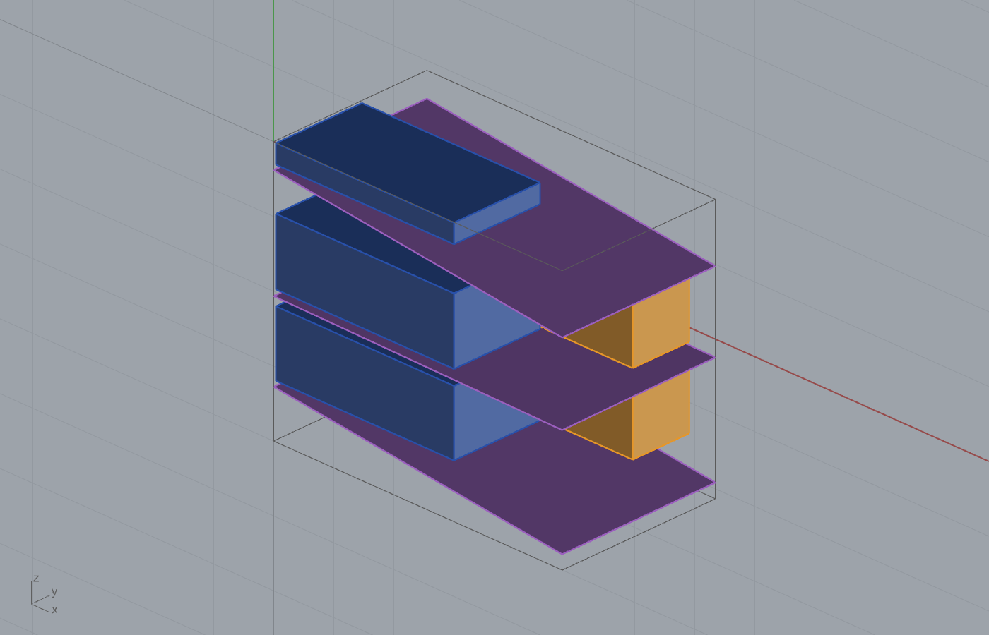
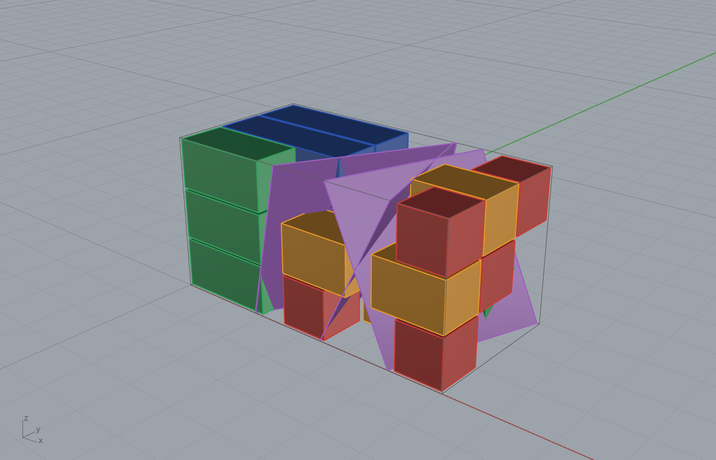
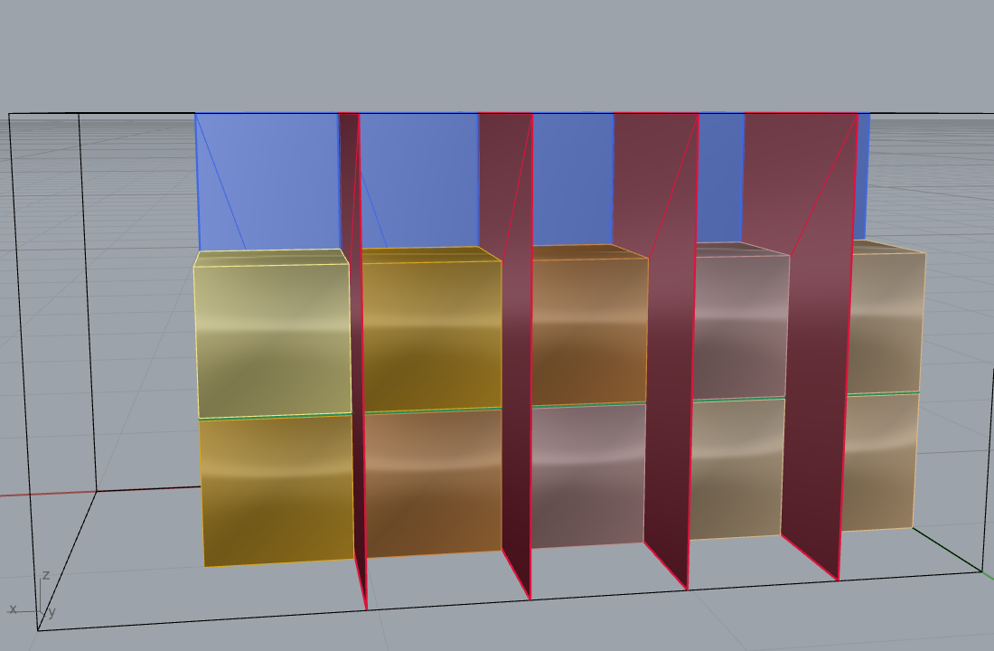
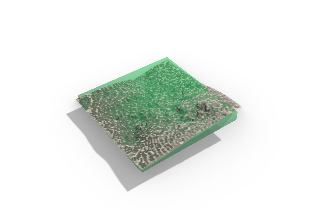
.ghand a light.3dm/.ghsimulation only, no PNG and no embeddable render (examples/05_artist_pointing_machine/). The figures in this chapter borrow from the engineer (04), guillotine (24), marble cost (25), and GPR marble (08) examples. Low (documentation gap). - Physical-marking tail not shipped. The georeferenced math (11.6) closes the scan-to-world transform, but no GH component yet turns the oblique bed-following cut planes into a georeferenced physical-marking output on the real block; example 08 documents the value the last-mile recovers but the automation is open. High (the named last-mile of example 08).
- Wire-saw v1 is planar only. Kerf compensation is skipped on a
non-planar cut curve (warned), and curved-surface cuts via ruled-surface
decomposition, variable wire tension, and bidirectional planning are v1.x
backlog (
WireSawToolpathAdapterComponent.cs:46-52,:188-191). The robot-mounted diamond-wire workflow remains research-grade per Zhang 2024 and Moult 2018. Medium. - G-code parser subset. v1 supports
G00/G01/G02/G03/G17/G20/G21/G90plusF S M N;G91incremental positioning andG18/G19non-XY arc planes are parsed but flagged, not solved (GCodeParserComponent.cs:296-303). Vendor extensions are deferred. Low (graceful warnings, not failures). - Robot adapters depend on third-party plugins. The KUKAprc command
components are paid-tier, and the visose/Robots plugin must be installed
separately (Frahan does not bundle
Robots.dll); the packaging decision is open (PlanesToRobotTargetsComponent.cs:30-37). Low. - Fit-in-block is axis-aligned. v1 matches sorted extents largest-to-
largest; a sculpture that fits only in a tilted orientation is reported as
not fitting. OBB-exact orientation search is deferred
(
FitInBlockComponent.cs:18-21). Low. - Carving Stages input order is load-bearing. Reordering the inputs breaks
canvases saved against the proven layout (the v2 regression); the order must
stay frozen, and heavy scans must be decimated before carving (KB-1/KB-2)
(
CarvingStagesComponent.cs:18-23;examples/05_artist_pointing_machine/README.md). Medium.
References (this chapter)
- ISO 6983-1:2009. Automation systems and integration — Numerical control of machines — Program format and definitions of address words — Part 1: Data format for positioning, line motion and contouring control systems. International Organization for Standardization.
- Horn, B.K.P. (1987). Closed-form solution of absolute orientation using unit quaternions. Journal of the Optical Society of America A 4(4):629-642. DOI 10.1364/JOSAA.4.000629. (Reference key [R103].)
- Zhang, Y., Wu, H., Wang, J., et al. (2024). Robotic diamond-wire cutting of stone with a six-axis arm and end-effector wire saw. Journal of Computational Design and Engineering 11(6):75-85. DOI 10.1093/jcde/qwae094. (Robot-mounted diamond-wire precedent; distinct from the block-cutting MATLAB toolbox Zhang et al. 2024, reference key [R145].)
- Moult, S., Weir, J., Fernando, S. (2018). Robotic diamond-wire bandsaw cutting of stone with a portable end-effector. University of Sydney (proceedings reference, cited in source).
- Konstanty, J.S. (2021). The mechanics of sawing granite with diamond wire. International Journal of Advanced Manufacturing Technology 116:2591-2597. DOI 10.1007/s00170-021-07577-3. (Diamond-wire kerf mechanics; reference key [R27].)
- Bowring, B.R. (1976). Transformation from spatial to geographical coordinates. Survey Review 23(181):323-327. DOI 10.1179/sre.1976.23.181.323.
- Karney, C.F.F. (2011). Transverse Mercator with an accuracy of a few nanometres. Journal of Geodesy 85(8):475-485. DOI 10.1007/s00190-011-0445-3.
- Snyder, J.P. (1987). Map Projections: A Working Manual. USGS Professional Paper 1395.
- Graham, R.L. (1969). Bounds on multiprocessing timing anomalies. SIAM Journal on Applied Mathematics 17(2):416-429. DOI 10.1137/0117039. (Greedy list scheduling, cited by the fabrication-prep handling lineage.)
- Braumann, J., Brell-Cokcan, S. KUKA|prc — parametric robot control for Grasshopper. Association for Robots in Architecture, Vienna. https://www.robotsinarchitecture.org/kukaprc
- Soler, V. Robots — a plugin for programming industrial robots in Grasshopper (MIT). https://github.com/visose/Robots